Oral restoration and correction auxiliary device

An auxiliary device and dental prosthesis technology, applied in the field of medical devices, can solve the problems of no product, inability to remove monitoring, low efficiency, etc., and achieve the effect of accurate results

Inactive Publication Date: 2019-07-12
王娟
View PDF12 Cites 1 Cited by
  • Summary
  • Abstract
  • Description
  • Claims
  • Application Information

AI Technical Summary

Problems solved by technology

The removal of the adhesive is very troublesome. The method of grinding is firstly inefficient, and secondly, the removal effect is not good.
Although some people use laser to re

Method used


Image

  • Oral restoration and correction auxiliary device
  • Oral restoration and correction auxiliary device

Examples


Embodiment 1

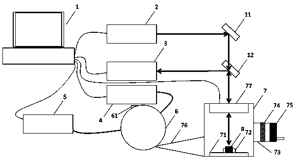
[0030] combine figure 1 , an auxiliary device for oral restoration and correction, characterized in that it includes a computer 1, a first laser 2, a first optical analyzer 3, a second laser 4, a second optical analyzer 5, a gas detection ball 6 and an ablation cylinder 7 ;

[0031] The computer 1 is connected to the first laser 2, the first optical analyzer 3, the second laser 4, and the second optical analyzer 5;

[0032] The first laser 2 emits laser light to ablate the orthodontic brackets in the ablation cylinder 7 to remove the surface adhesive, and the first optical analyzer 3 analyzes the plasma generated during the ablation process; the ablation cylinder 7 The gas produced inside enters the gas detection ball 6, the second laser 4 emits laser light to irradiate the inside of the gas detection ball 6, the second optical analyzer 5 analyzes the light absorption inside the gas detection ball 6, and sends the detection result to the computer 1.

[0033] The ablation cyl...

Embodiment 2

[0044] A method for cleaning orthodontic brackets using the above-mentioned device is characterized in that it comprises the following steps:

[0045] Step 1 Take the ablation platform 71 out of the ablation cylinder 7, fix the orthodontic bracket 8 on the clamp 72 of the ablation platform 71, and put the ablation platform 71 back into the ablation cylinder 7 to ensure ablation The seal between the platform 71 and the ablation cylinder 7;

[0046] Step 2 Start the intake pump 75 to make dry air enter the ablation cylinder 7 and discharge from the top of the optical analysis sphere;

[0047] Step 3 The computer 1 controls the first laser 2 to emit weak continuous light, and the vibrating mirror device 77 irradiates the laser light emitted by the first laser 2 to the position of the orthodontic bracket 8, and the computer 1 detects whether the first optical analyzer 3 can receive the light If the optical signal cannot be received, disassemble the machine for inspection;

[0048]...

Embodiment 3

[0052] Step 3 increases the computer to adjust the power of the first laser, so that the laser can only remove the adhesive, and will not damage the bracket itself.

[0053] Step 5 is changed to when the elements of the adhesive component analyzed by the first optical analyzer 3 fall below the threshold value, and at the same time, the absorption peak of the gas generated by the adhesive ablation in the absorption spectrum measured by the second optical analyzer 5 When the position does not drop within a certain period of time, the computer 1 controls the first laser 2 and the second laser 4 to stop working, and the cleaning process is completed.


PUM


Abstract

The invention relates to an oral restoration and correction auxiliary device and provides a novel orthodontic bracket adhesive removing mode. Laser is adopted for ablating the surface of an orthodontic bracket, plasma is formed, and adhesive is removed; meanwhile, the plasma produced when the adhesive is removed is utilized for performing laser breakdown spectroscopy analysis, removed components are obtained, and the removing process can be monitored in real time; and a novel gas detecting method is designed by the invention when the adhesive is removed, gas is introduced into a spherical integrator, light absorption detection is performed in the integrator, and detection results are made more accurate.

Description

technical field [0001] The invention relates to the field of medical equipment, in particular to an auxiliary device for oral restoration and correction. Background technique [0002] Bracket is an important part of fixed orthodontic technology. It is directly bonded to the surface of the crown with adhesive, and the arch wire passes through the bracket to exert various types of orthodontic force on the tooth. Brackets are made of stainless steel, bioceramic or composite resin, and their main function is to fix the arch wire, so that the arch wire can play a better role and transmit the orthodontic force, so as to control the three-dimensional movement of the teeth and achieve the purpose of orthodontic treatment. [0003] At present, the brackets sometimes fall off accidentally and need to be reinstalled, and the reinstallation of the new brackets will cause a lot of inconvenience because the installation time of the new brackets is different from that of the original brack...

Claims


Application Information

Patent Timeline
IPC IPC(8): B08B7/00A61C7/16
CPCA61C7/16B08B7/0042
Inventor 王娟
Owner 王娟
Why Eureka
Try Eureka