Extruding wheel of continuous extruding machine

A technology of extrusion wheel and extrusion machine, applied in metal extrusion forming tools, metal extrusion, metal processing equipment, etc., can solve the problem of extrusion wheel scrapping, reduce stress value, and reduce equipment operating costs Effect

Pending Publication Date: 2019-07-12
大连康丰科技有限公司
View PDF0 Cites 0 Cited by
  • Summary
  • Abstract
  • Description
  • Claims
  • Application Information

AI Technical Summary

Problems solved by technology

[0003] Since the extrusion wheel is subjected to the extrusion force during operation, and the friction between the extrusion wheel and the billet makes the vicinity of the extrusion wheel groove and the outer surface of the extrusion wheel still in a high temperature state, in order to control the extrusion temperature, the traditional The continuous extrusion machine generally carries out water cooling on the inner surface of the extrusion wheel. After working for a period of time, the extrusion wheel will gradually crack from the inner surface to the outer surface. When it is completely cracked, the extrusion wheel will be scrapped. One of the main ways of wheel scrapping

Method used


Image

  • Extruding wheel of continuous extruding machine
  • Extruding wheel of continuous extruding machine
  • Extruding wheel of continuous extruding machine

Examples


Embodiment 1

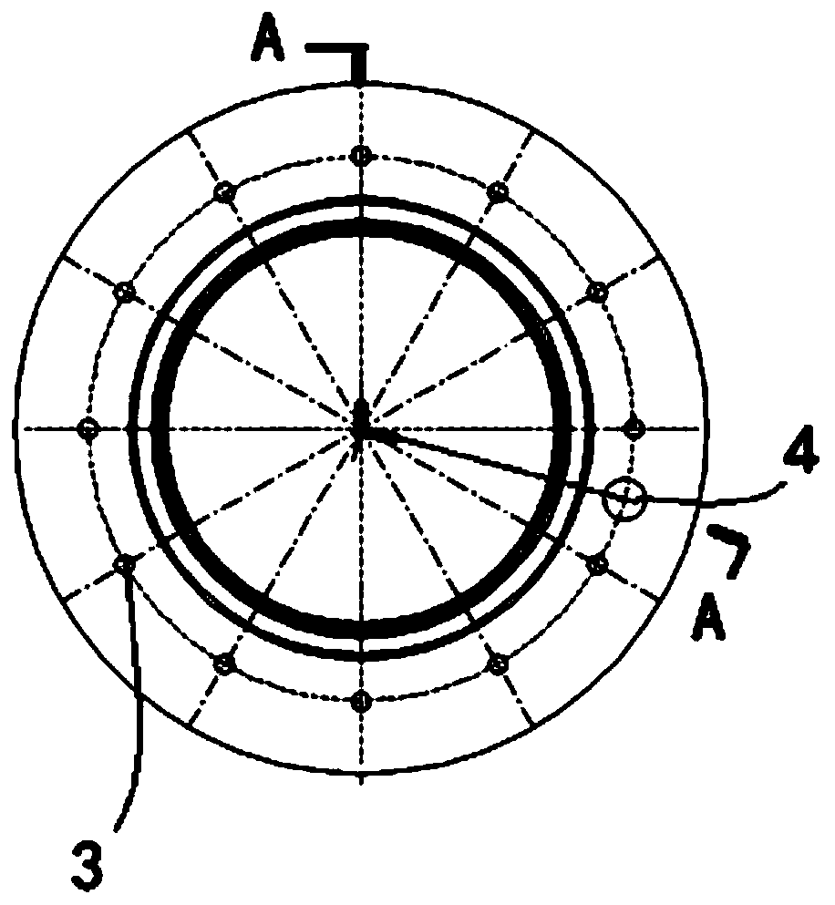
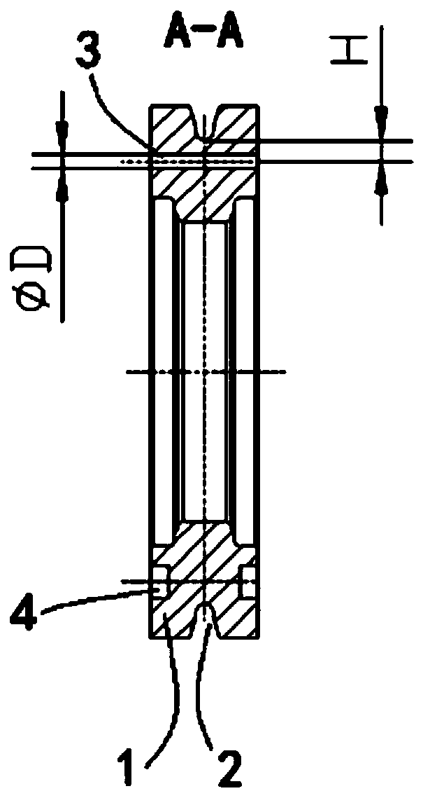
[0016] Such as Figure 1-Figure 2 As shown, an extrusion wheel of a continuous extrusion machine, the extrusion wheel 1 is provided with a circular groove 2 in the circumferential direction, and the extrusion wheel 1 is distributed along the circumferential direction with a plurality of grooves passing through the extrusion wheel 1. Cooling through hole 3, there is a distance H between the center line of the cooling through hole 3 and the bottom of the groove 2, and the center line of the cooling through hole 3 is perpendicular to the end face of the extrusion wheel, that is, the center line of the cooling through hole 3 and the extrusion wheel 1 The centerlines are parallel, and the end face of the extrusion wheel is provided with a pin hole 4 that does not go through the extrusion wheel 1 .

[0017] The diameter D of the cooling through hole 3 is 10 mm, the distance H between the center line of the cooling through hole 3 and the bottom of the groove is 28 mm, and the number ...

Embodiment 2

[0020] The structure and connection relationship of each part of the extrusion wheel of a continuous extrusion machine described in this embodiment are the same as those in Example 1, the difference is that the cooling through hole 3 is 15° from the axis of the extrusion wheel 1. °; the diameter of the cooling through hole 3 is 6 mm, the distance H from the centerline of the cooling through hole 3 to the bottom of the groove is 15 mm, and the number of cooling through holes 3 is 20; the number of the pin hole 4 is 1 ; The inner hole of the extrusion wheel is provided with circular arc grooves for installing transmission keys to transmit torque, the number of the circular arc grooves is 4-16, and the radius of the circular arc grooves is 4-20mm.

Embodiment 3

[0022] The structure and connection relationship of each part of the extrusion wheel of a continuous extrusion machine described in this embodiment are the same as those in Example 1, the difference is: the cooling through hole 3 is 30 degrees to the axis of the extrusion wheel 1 °; the diameter of the cooling through hole 3 is 15mm, the distance H between the centerline of the cooling through hole 3 and the bottom of the groove is 40mm, and the number of cooling through holes 3 is 8; the number of the pin holes 4 is 16 ; The inner hole of the squeeze wheel is provided with internal splines for torque transmission.


PUM

PropertyMeasurementUnit
radiusaaaaaaaaaa

Abstract

The invention provides an extruding wheel of a continuous extruding machine, and relates to the technical field of continuous extruding and continuous coating of nonferrous metals such as copper and aluminum. The extruding wheel is provided with at least one annular groove in the circumferential direction, a plurality of cooling through holes penetrating through the extruding wheel are distributedin the circumferential direction of the extruding wheel, a distance is reserved between the center lines of the cooling through holes and the bottoms of the grooves, the axes of the cooling through holes are parallel to the axis of the extruding wheel or a certain spatial angle is reserved between the axes of the cooling through holes and the axis of the extruding wheel, and a pin hole which doesnot penetrate through the extruding wheel is formed in the end surface of the extruding wheel. According to the extruding wheel, by changing a cooling water channel of the extruding wheel, the temperature distribution and the stress state of the extruding wheel are changed while the temperature of the grooves of the extruding wheel is controlled and the softening of the high temperature areas ofthe grooves of the extruding wheel is relieved, stress value of dangerous damage points of the extrusion wheel is reduced, so that the rotating speed of the extruding wheel can be increased, the production efficiency is remarkably improved, the service life of the extruding wheel and a cavity is prolonged, and the operating cost of equipment is reduced.

Description

technical field [0001] The invention relates to the technical field of continuous extrusion and continuous coating of non-ferrous metals such as copper and aluminum, in particular to an extrusion wheel of a continuous extrusion machine. Background technique [0002] At present, in the continuous extrusion and continuous coating of copper, aluminum and other non-ferrous metals and cable manufacturing in the wire and cable industry, the continuous extrusion machine is mainly used for continuous extrusion and continuous coating of copper, aluminum and alloy metals, and is also used for Wire and cable manufacturing for the wire and cable industry. The working principle of the continuous extrusion machine is: the extrusion wheel is rotated by the motor, and the billet enters the wheel groove of the extrusion wheel. In the arc-shaped extrusion chamber, under the action of high pressure and high temperature generated by friction, the copper and aluminum rod blanks are extruded thr...

Claims


Application Information

Patent Timeline
Patent Type & Authority Applications(China)
IPC IPC(8): B21C25/00B21C29/00
CPCB21C25/00B21C29/00
Inventor 闫志勇张旭易飞
Owner 大连康丰科技有限公司
Why Eureka
Try Eureka