Anti-loosening quick-replacing nut

An anti-loosening and nut technology, applied in the direction of nuts, screws, bolts, etc., can solve the problems of poor anti-loosening performance of anti-loosening quick-change nuts and affecting the personal safety of staff.

Pending Publication Date: 2019-07-12
SHANDONG WEIDA MASCH CO LTD
View PDF0 Cites 0 Cited by
  • Summary
  • Abstract
  • Description
  • Claims
  • Application Information

AI Technical Summary

Problems solved by technology

[0003] The main purpose of the present invention is to provide an anti-loose quick-change nut to solve the problem in ...

Method used


Image

  • Anti-loosening quick-replacing nut
  • Anti-loosening quick-replacing nut
  • Anti-loosening quick-replacing nut

Examples


Embodiment 1

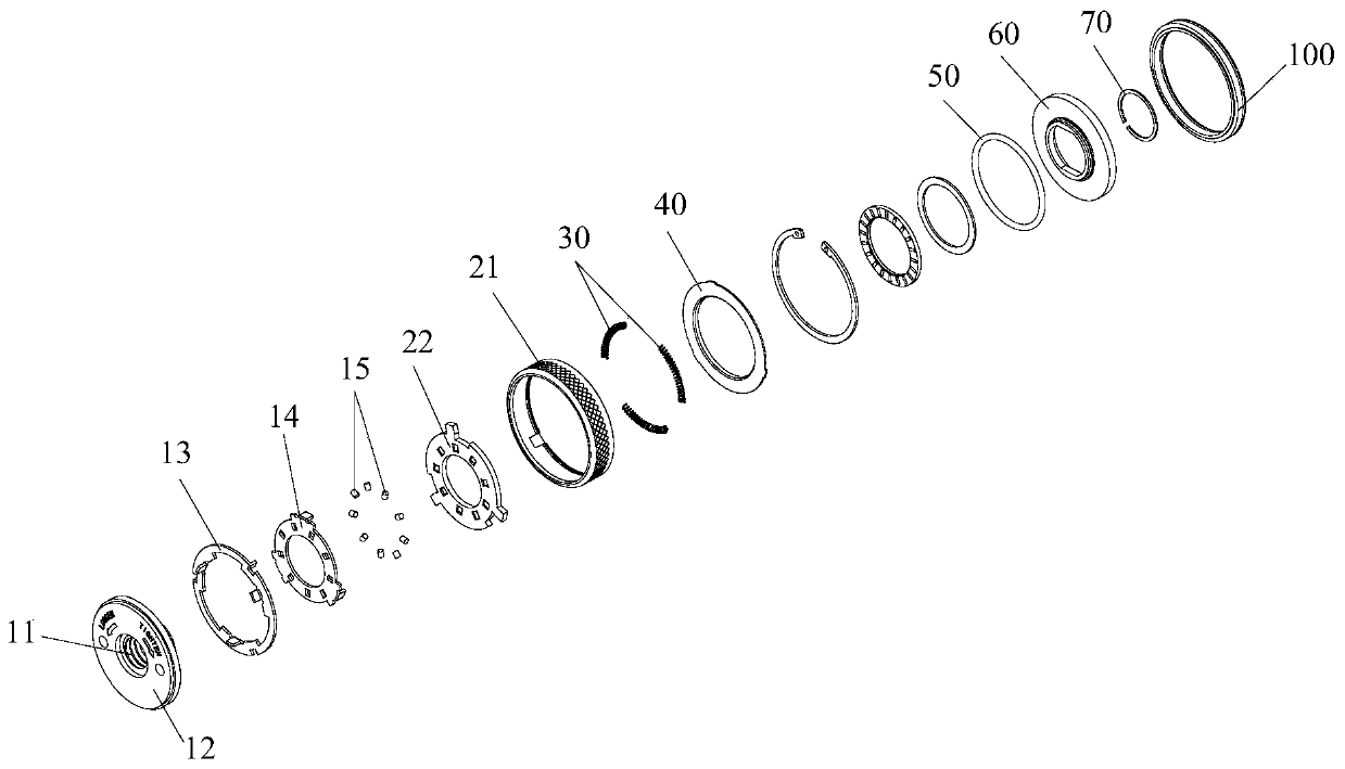
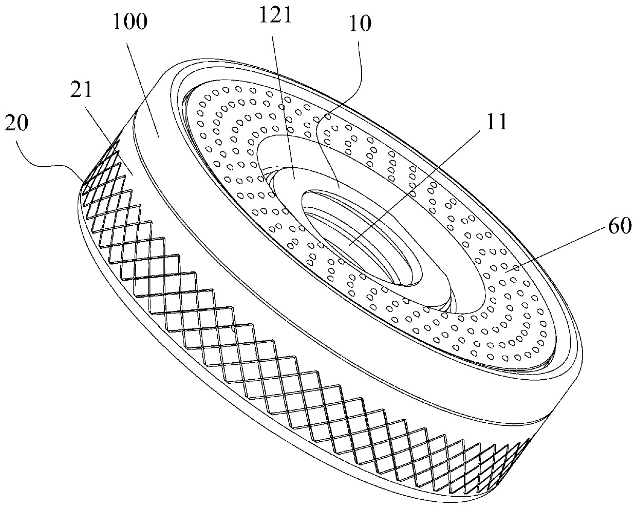
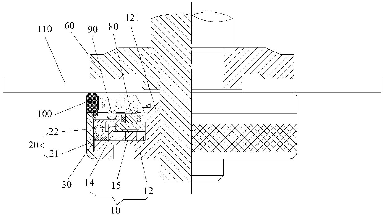
[0038] Such as Figure 1 to Figure 3 As shown, the anti-loosening quick change nut includes a nut assembly 10 , a screw assembly 20 and an anti-loosening structure 100 . Wherein, the nut assembly 10 has an internal thread 11 . The screw assembly 20 includes a sleeve structure 21 and a partition structure 22. The sleeve structure 21 is sleeved outside the nut assembly 10. The partition structure 22 is detachably connected to the sleeve structure 21 and is located in the sleeve structure 21. The partition structure 22 is connected to the sleeve structure 21. The nut assembly 10 is non-rotatingly connected so that the screw assembly 20 has a static anti-rotation state relative to the nut assembly 10 . When the screw assembly 20 is in the anti-rotation state, the screw assembly 20 can drive the nut assembly 10 to rotate together. The anti-loosening structure 100 is arranged on the side of the screw assembly 20 facing the to-be-fastened piece 110 to increase the frictional force b...

Embodiment 2

[0054] The difference between the anti-loosening quick-change nut in the second embodiment and the first embodiment is that the structure of the anti-loosening quick-change nut is different.

[0055] Such as Figure 4 to Figure 6 As shown, the nut assembly 10 includes a nut body 12, the nut body 12 has a through hole 123 and a mounting portion 124 communicating with the through hole 123, the inner wall of the through hole 123 has an internal thread 11, and the anti-loosening quick change nut also includes an auxiliary anti-loosening structure 130 . Wherein, the auxiliary anti-loosening structure 130 is arranged in the installation part 124, and the auxiliary anti-loosening structure 130 is in contact with the to-be-fastener 110 pierced in the via hole 123, so as to increase the gap between the anti-loosening quick-change nut and the to-be-fastener 110. The frictional force prevents the anti-loosening quick-change nut from rotating relative to the component 110 to be fastened....

Embodiment 3

[0062] The difference between the anti-loosening quick-change nut in the third embodiment and the second embodiment is that the structure of the auxiliary anti-loosening structure 130 is different.

[0063] Such as Figure 7 to Figure 10 As shown, the auxiliary anti-loosening structure 130 includes a locking section 131 and a tapered section 132 connected in sequence, and the size of the tapered section 132 gradually increases along the direction from the locking section 131 to the tapered section 132 . Wherein, the tapered section 132 is connected with the mounting portion 124 to connect the auxiliary anti-loosening structure 130 with the nut body 12 , and the clamping section 131 is clamped with the component to be fastened 110 passing through the through hole 123 . In this way, when the anti-loosening quick-change nut is tightened on the component 110 to be fastened (such as the motor shaft), the clamping section 131 will be deformed to a certain extent, so that the frictio...


PUM


Abstract

The invention provides an anti-loosening quick-replacing nut. The anti-loosening quick-replacing nut comprises a nut assembly, a screwing assembly and an anti-loosening structure, wherein the nut assembly is provided with an internal thread; the screwing assembly comprises a sleeving structure and a separating structure, the sleeving structure is arranged outside the nut assembly, the separating structure and the sleeving structure are detachably connected and located in the sleeving structure, the separating structure is in rotation stopping connection with the nut assembly so that the screwing assembly can have the rotation stopping state which is static relative to the nut assembly, and when the screwing assembly is in the rotation stopping state, the screwing assembly can drive the nutassembly to rotate together; and the anti-loosening structure is arranged on the side, facing towards a to-be-fastened piece, of the screwing assembly so that the friction force between the screwingassembly and the to-be-fastened piece can be increased, and the anti-loosening structure is made of a friction resistance material. Through the anti-loosening quick-replacing nut, the problem that inthe prior art, an anti-loosening quick-replacing nut is poor in loosening resistance, and the personal safety of staff is influenced is effectively solved.

Description

technical field [0001] The invention relates to the technical field of fasteners, in particular to an anti-loosening quick-change nut. Background technique [0002] At present, nuts are applied to various devices in the mechanical field (such as angle grinders) to achieve the purpose of connection and tightening. However, after the angle grinder is stopped, due to the large inertia of the angle grinder, the nut will be loosened, so that the slices fly out, endangering personal safety. Contents of the invention [0003] The main purpose of the present invention is to provide an anti-loose quick-change nut to solve the problem in the prior art that the anti-loose quick-change nut has poor anti-loose performance and affects the personal safety of workers. [0004] In order to achieve the above object, the present invention provides an anti-loosening quick-change nut, including: a nut assembly with internal threads; a screw assembly including a sleeve structure and a partitio...

Claims


Application Information

Patent Timeline
IPC IPC(8): F16B39/282F16B37/00
CPCF16B39/282F16B37/00
Inventor 张吉祥林鹏
Owner SHANDONG WEIDA MASCH CO LTD
Why Eureka
Try Eureka