
Bearing assembly

A technology of bearing components and bearings, applied in the direction of bearing components, shafts and bearings, rigid supports of bearing components, etc., can solve the problems of reduced service life and limited floating distance of spherical roller bearings at the floating end

Inactive Publication Date: 2019-07-12
SCHAEFFLER TECH AG & CO KG
View PDF0 Cites 0 Cited by
  • Summary
  • Abstract
  • Description
  • Claims
  • Application Information

AI Technical Summary

Problems solved by technology

[0004] However, since the outer ring of the non-locating bearing is in direct contact with the housing hole, when the shaft deforms, there will be relative movement between the two in the axial direction, resulting in a large friction force, which limits the floating distance. Resulting in reduced service life of non-locating spherical roller bearings

Method used


Image

  • Bearing assembly
  • Bearing assembly
  • Bearing assembly

Examples


Embodiment Construction

[0037] It can be known from the background technology that the outer ring of the non-locating bearing is in direct surface contact with the hole of the bearing housing. In the case of deformation of the shaft, there will be relative movement between the two in the axial direction, resulting in a large friction force, which limits the floating distance and reduces the life of the non-locating bearing.

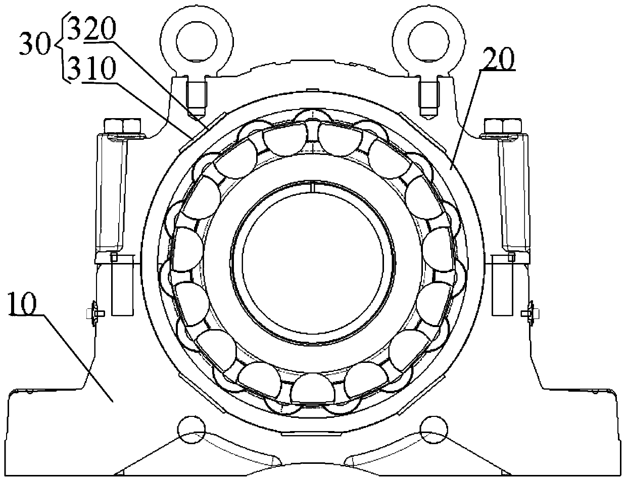
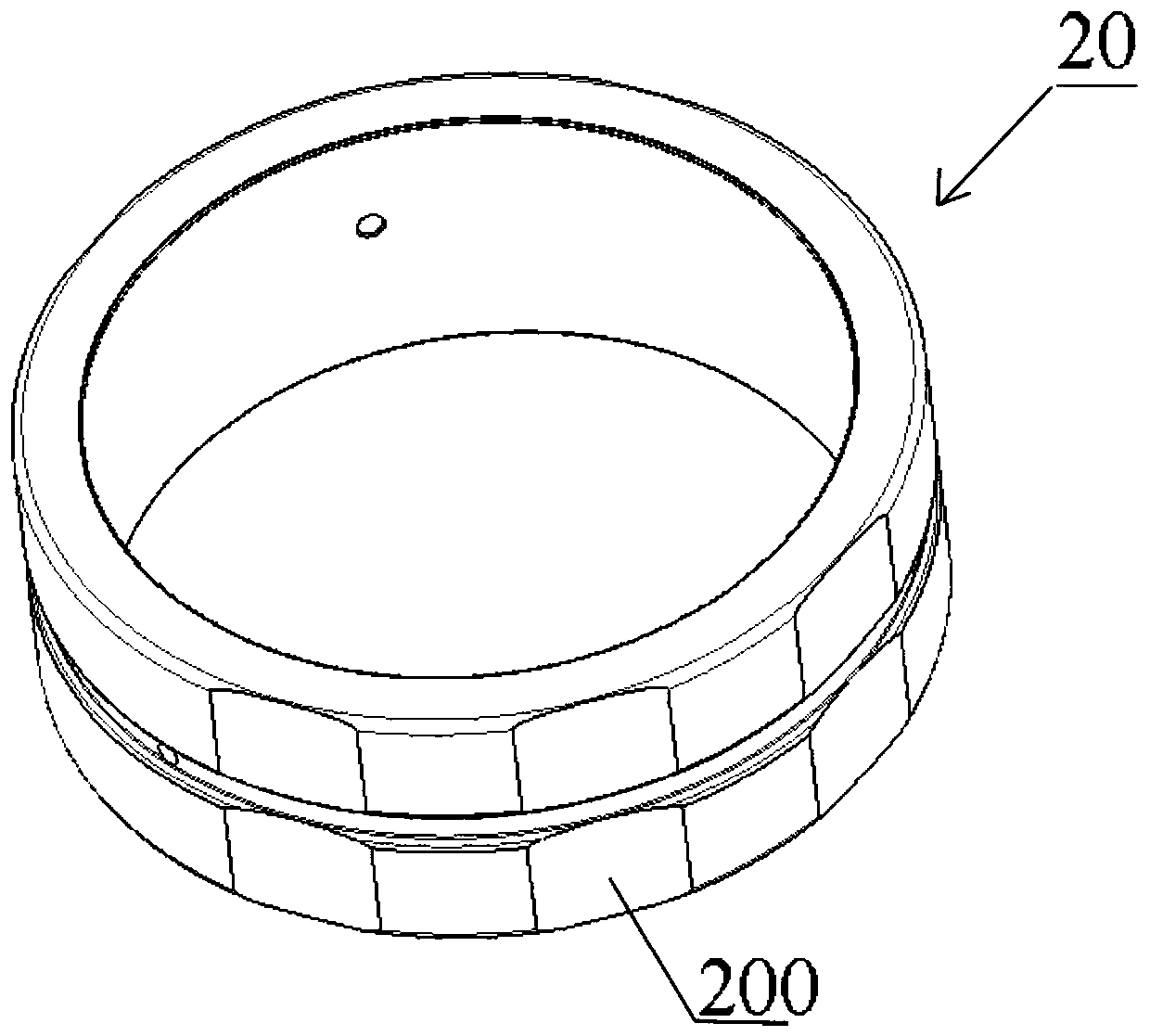
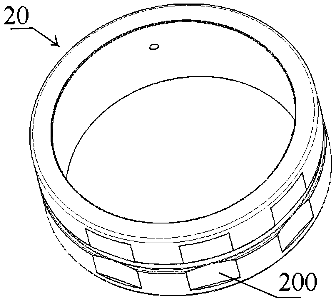
[0038] In order to improve the floating distance and service life of the non-locating bearing, the embodiment of the present invention provides a bearing assembly, by fixing wear-resistant parts on the hole wall of the bearing seat, and extending along the axial direction on the circumferential surface of the bearing outer ring. The groove of the outer ring of the bearing, and the wear-resistant parts are embedded in the groove of the outer ring of the bearing. When the shaft expands due to heat, the outer ring of the bearing is driven by the shaft to move relative to the bearing...


PUM


Abstract

The invention discloses a bearing assembly. The bearing assembly comprises a bearing seat, a bearing outer ring, and a wear-resistant part, wherein a bearing seat hole is formed in the bearing seat; the bearing outer ring is arranged in the bearing seat hole, the diameter of the bearing seat hole is greater than that of the bearing outer ring, and a bearing outer ring groove extending in the axialdirection of the bearing outer ring is formed in the circumferential face of the bearing outer ring; and the first end of the wear-resistant part is fixed on the hole wall of the bearing seat hole, the second end of the wear-resistant part is embedded into the bearing outer ring groove and makes contact with the bottom face of the bearing outer ring groove, and the wear-resistant part can do therelative axial motion in the bearing outer ring groove. By adding the wear-resistant part between the bearing seat and the bearing outer ring, the contact area of the surface friction produced by therelative axial motion between the bearing outer ring and the bearing seat is reduced, the wear area of the bearing outer ring is reduced accordingly, and the service life of the bearing is prolonged;and further, as the diameter of the bearing seat hole is greater than that of the bearing outer ring, the wear-resistant part is protruded from the bearing outer ring groove, namely, the radial gap between the bearing seat and the bearing outer ring is increased, and the floating distance of the bearing is increased accordingly.

Description

technical field [0001] The embodiments of the present invention relate to the technical field of machinery, and in particular to a bearing assembly. Background technique [0002] Bearing configurations include the following three types: fixed and non-locating bearing configurations (the bearing at one end of the shaft is fixed and the bearing at the other end of the shaft is floating), pre-adjusted bearing configurations (the bearings at both ends of the shaft are fixed), and "floating" Bearing arrangement (bearings at both ends of the shaft are floating). [0003] Fixed / loose bearing systems in typical industrial applications are designed to accommodate thermal expansion and contraction of the shaft. In this system, the bearing arrangement at one end of the shaft must be able to locate the shaft axially. This process is accomplished by securing the bearing on the shaft and in the housing. The bearing arrangement at the other end of the shaft is a non-locating bearing des...

Claims


Application Information

Patent Timeline
IPC IPC(8): F16C35/077F16C33/58
CPCF16C35/077F16C33/58
Inventor 韩慧敏刘际轩
Owner SCHAEFFLER TECH AG & CO KG
Learn More