Near-field tunnel blasting vibration dynamic strain testing method for tunnel under construction

A blasting vibration and testing method technology, applied in the direction of electric/magnetic solid deformation measurement, electromagnetic measuring device, etc., can solve the problems of large blasting vibration, difficult to zero dynamic strain value, interference, etc., to reduce vibration friction and blasting vibration Shock, the effect of reducing disturbance

Inactive Publication Date: 2019-07-12
THE 4TH ENG OF CHINA RAILWAY 5TH ENG GROUP +2
View PDF9 Cites 9 Cited by
  • Summary
  • Abstract
  • Description
  • Claims
  • Application Information

AI Technical Summary

Problems solved by technology

It can be seen that the blasting vibration dynamic strain peak value of 4000με obtained by the test is far beyond the static allowable tensile strain value of concrete of 67με. Obviously, the blasting vibration dynamic strain value obtained by the test is wrong and has no reference at all.
Moreover, because there is no reliable vibration reduction and reinforcement treatment for the data line and each joint, it is difficult to return the dynamic strain value of each section after the blasting to zero.
[0005] For tunnels under construction, the blasting vibration dynamic strain test in the vicinity of the tunnel has the following characteristics: (1) The strain test location is close to the tunnel blasting excavation area, and the blasting vibration is extremely large, which greatly interferes with the dynamic strain test results; (2) The tunnel has only completed the initial support, and the surface of the tunnel strain test is extremely rough; (3) The construction environment of the tunnel under construction is complex, and there are many interference factors, such as the difficult grounding of the dynamic signal acquisition instrument, strong electromagnetic interference from the surrounding electric welding, etc., which can easily affect the test results

Method used


Image

  • Near-field tunnel blasting vibration dynamic strain testing method for tunnel under construction
  • Near-field tunnel blasting vibration dynamic strain testing method for tunnel under construction
  • Near-field tunnel blasting vibration dynamic strain testing method for tunnel under construction

Examples


Embodiment 1

[0067] The Beijing-Zhangjiakou high-speed railway in this embodiment is a key construction project planned and implemented by the state, and it is also a supporting project for Beijing-Zhangjiakou to jointly host the Olympic Games in 2022. The Badaling Great Wall Station of the Beijing-Zhangjiakou High-speed Railway is currently the deepest buried high-speed railway underground station in China. It is located under the Badaling Great Wall Scenic Area and in the New Badaling Tunnel.

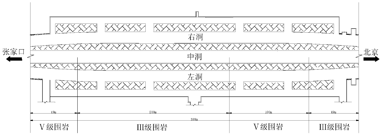
[0068] see figure 2 , figure 2 It is a division diagram of the surrounding rock grades of the three-hole separation section in Example 1 of the present invention. The platform layer of Badaling Great Wall Station is a separated section with three tunnels. It is composed of three tunnels, the main line cavern and the departure line caverns on both sides. Monzogranite, the surrounding rock grades are mainly grade III and grade V.

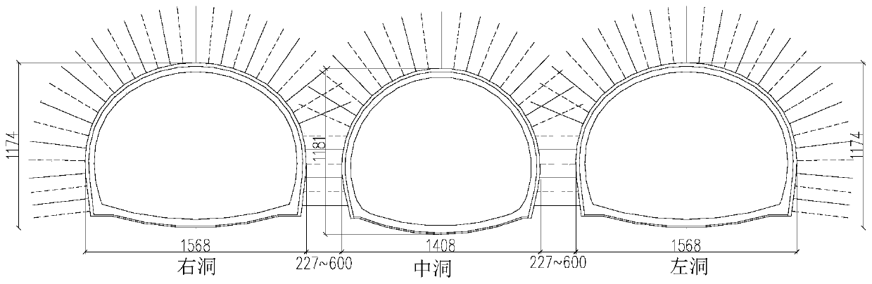
[0069] see image 3 , image 3 It is a cross-sectional view o...


PUM


Abstract

The invention provides a near-field tunnel blasting vibration dynamic strain testing method for a tunnel under construction. The method comprises the following steps: S1, arranging testing points on aprimary support of the tunnel, and polishing the surfaces of the testing points; S2, adhering strain gages to the surface of each testing point, leading out connecting wires, and coating the outsideof each strain gage with protection glue for fixation; S3, arranging one temperature compensation gage for each strain gage, adhering each temperature compensation gage onto a compensation block, leading out a connecting wire, and coating the outside of each temperature compensation gage with protection glue for fixation; S4, connecting the strain gages and the temperature compensation gages withcorresponding bridge boxes through data cables, connecting the strain gages and the temperature compensation gages in the corresponding bridge boxes in a half-bridge manner, and carrying out vibrationattenuation processing; S5, reinforcing joints with the data cables; S6, connecting the bridge boxes with a dynamic signal acquisition device, and transmitting real-time data acquired by the dynamicsignal acquisition device to a computer; and S7, grounding the dynamic signal acquisition device. The method provided by the invention has the advantage that near-field tunnel blasting vibration dynamic strains of the tunnel under construction can be accurately tested.

Description

technical field [0001] The invention relates to the technical field of tunnel engineering, in particular to a method for testing the blasting vibration dynamic strain of a nearby tunnel under construction. Background technique [0002] Blasting vibration test is a test method often used to evaluate the impact of tunnel engineering blasting on surrounding chambers and adjacent structures. The test indicators mainly include velocity, acceleration, displacement, stress or strain, etc. In the on-site tunnel blasting monitoring, the most commonly used testing and evaluation indicators are still only monitoring the blasting vibration velocity, and there is no item to monitor the blasting dynamic strain. This is mainly because the blasting vibration velocity test is relatively simple and mature. The blasting vibration velocity of the tunnel is difficult to reflect the tunnel stress state of the rock mass under the blasting load, and it is also difficult to directly judge whether th...

Claims


Application Information

Patent Timeline
Patent Type & Authority Applications(China)
IPC IPC(8): G01B7/16
CPCG01B7/18
Inventor 罗驰杨新安王浩蒋思罗都颢肖承倚李坤刘臻武
Owner THE 4TH ENG OF CHINA RAILWAY 5TH ENG GROUP
Why Eureka
Try Eureka