Method and system for automatic detection of parts based on industrial robots

An industrial robot and automatic detection technology, which is applied in the direction of instruments, measuring devices, scientific instruments, etc., can solve the problems of unstable detection results, difficult management of inspection tools, long detection time, etc.

Active Publication Date: 2021-08-03
精诚工科汽车系统有限公司
View PDF7 Cites 0 Cited by
  • Summary
  • Abstract
  • Description
  • Claims
  • Application Information

AI Technical Summary

Problems solved by technology

However, the manual inspection method requires quality inspectors to have superb comprehensive skills, a large number of high-precision inspection tools and a long inspection time (such as 20 minutes) for each component.
Limited by the skills of the quality inspectors and the accuracy of the inspection tools, etc., the test results are unstable, the management of the inspection tools is difficult, and the inspection time is long
[0003] In order to solve the above-mentioned problems in the manual inspection method, a method of manual scanning inspection using non-contact optical three-dimensional measuring equipment is proposed in the current related art, but the method of manual scanning inspection using non-contact optical three-dimensional measuring equipment requires Quality inspectors move the testing equipment to various places that need to be measured, which cannot meet the testing efficiency requirements of mass-produced products that require strict quality control

Method used


Image

  • Method and system for automatic detection of parts based on industrial robots
  • Method and system for automatic detection of parts based on industrial robots
  • Method and system for automatic detection of parts based on industrial robots

Examples


Embodiment Construction

[0044] It should be noted that, in the case of no conflict, the embodiments and features in the embodiments of the present invention can be combined with each other.

[0045] In addition, the industrial robot mentioned in the embodiments of the present invention refers to a robot equipped with a vision system or a camera device, which is widely used to detect defects of parts (such as auto parts).

[0046] The present invention will be described in detail below with reference to the drawings and in combination with embodiments.

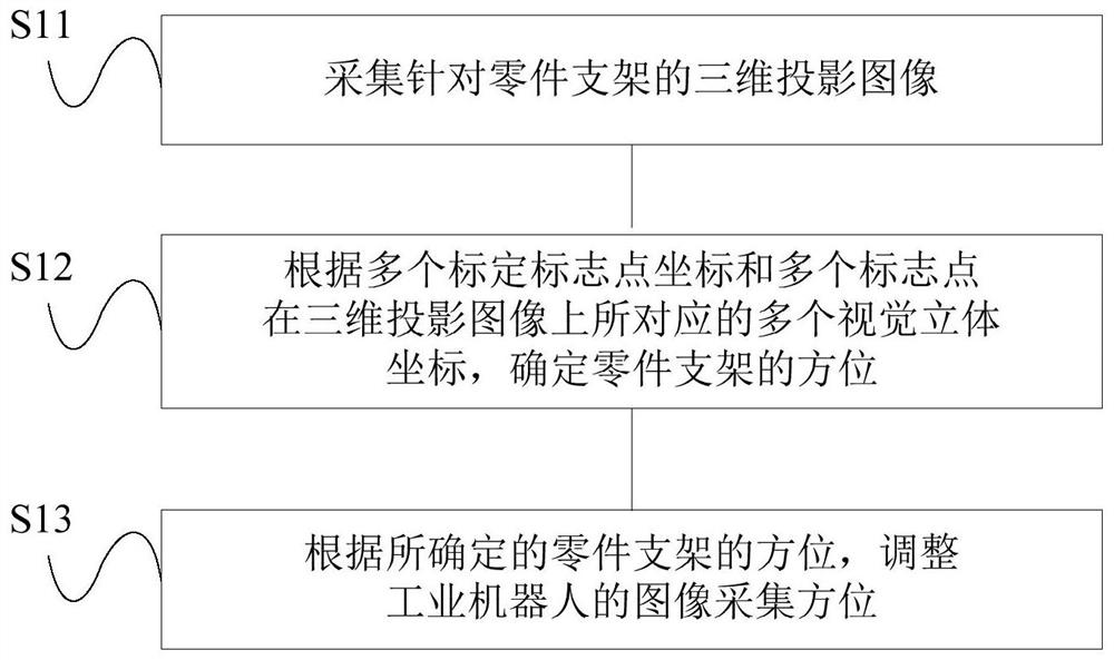
[0047] Such as figure 1 As shown, the automatic detection method for parts based on industrial robots according to an embodiment of the present invention includes:

[0048] S11. Acquire a three-dimensional projection image for the part bracket, wherein the part bracket is marked with a plurality of preset marker points corresponding to the coordinates of a plurality of calibration marker points in the robot tool coordinate system, and the part bracke...


PUM


Abstract

The present invention relates to the technical field of industrial robots, and provides a method and system for automatic detection of parts based on industrial robots. A plurality of marker points corresponding to the coordinates of a plurality of calibration marker points in the tool coordinate system, and the part bracket is used to place the part to be detected; according to the coordinates of the multiple calibration marker points and the coordinates of the multiple marker points The orientation of the part support is determined according to the plurality of visual stereo coordinates corresponding to the three-dimensional projection image; and the image acquisition orientation of the industrial robot is adjusted according to the determined orientation of the part support. As a result, the robot can adaptively adjust the image acquisition orientation according to the marker points, realizing the commonality of the bracket and the arbitrariness of the location, and meeting the detection efficiency requirements for mass-produced products.

Description

technical field [0001] The invention relates to the technical field of industrial robots, in particular to an automatic detection method and system for parts based on industrial robots. Background technique [0002] In the production and assembly process of auto parts and sub-assembly sheet metal parts, it is necessary to inspect the structural dimensional tolerances of parts in batches. At present, the inspection method of the structural dimensional tolerance of parts is mainly manual inspection using the method of inspection tool + measuring tool. However, the manual inspection method requires quality inspectors to have superb comprehensive skills, a large number of high-precision inspection tools are required, and each component requires a long inspection time (such as 20 minutes). Limited by the skills of the quality inspectors and the accuracy of the inspection tools, etc., the test results are unstable, the management of the inspection tools is difficult, and the insp...

Claims


Application Information

Patent Timeline
Patent Type & Authority Patents(China)
IPC IPC(8): G01B11/24G01N21/01G01N21/95
CPCG01B11/2433G01N21/01G01N21/9515
Inventor 赵志涛高祥李栋李建和何国川张光辉常亮刘占一周迪尹晓贺
Owner 精诚工科汽车系统有限公司
Why Eureka
Try Eureka