
Electromagnetic wire for high-power wind driven generator

A technology of wind power generators and electromagnetic wires, applied to circuits, insulated cables, electrical components, etc., can solve problems such as low motor slot fullness, copper wires are easily deformed, and insulation damage, etc., to achieve reduced overall strength and hardness, and regular and beautiful shapes , easy processing and forming effect

Pending Publication Date: 2019-07-12
SUZHOU GUANLONG MAGNET WIRE
View PDF0 Cites 1 Cited by
  • Summary
  • Abstract
  • Description
  • Claims
  • Application Information

AI Technical Summary

Problems solved by technology

[0002] Electromagnetic wire products are mainly used in the stator coils of high-power 7MW and above direct-drive wind turbines. The size specifications of the electromagnetic wires used in the prior art are usually 4mm×16mm and above. When winding into shuttle coils, the size is usually 11 to 12 Turns of a single electromagnetic wire are stacked together. Since the larger the specification of a single electromagnetic wire, the higher its strength and hardness, it takes a lot of force to draw it into a frame-shaped coil. The requirements for drawing equipment are very high. At the same time, the shape of the drawn coil is not regular and perfect. It is difficult to correct the shape in the subsequent baking process, and the electromagnetic wire is easily damaged during the forming process; The width is wider, and the copper wire is easily deformed at the R bend, which affects the insulation effect.
In addition, in the existing technology, in order to avoid the occurrence of insulation damage during processing, the insulation thickness is generally set at 0.70mm~0.75mm, and the insulation thickness is thicker, so that the motor slot fill rate is low and the efficiency is relatively low.

Method used


Image

  • Electromagnetic wire for high-power wind driven generator
  • Electromagnetic wire for high-power wind driven generator
  • Electromagnetic wire for high-power wind driven generator

Examples


Embodiment Construction

[0020] The technical solutions of the present invention will be further described below in conjunction with the accompanying drawings and specific embodiments.

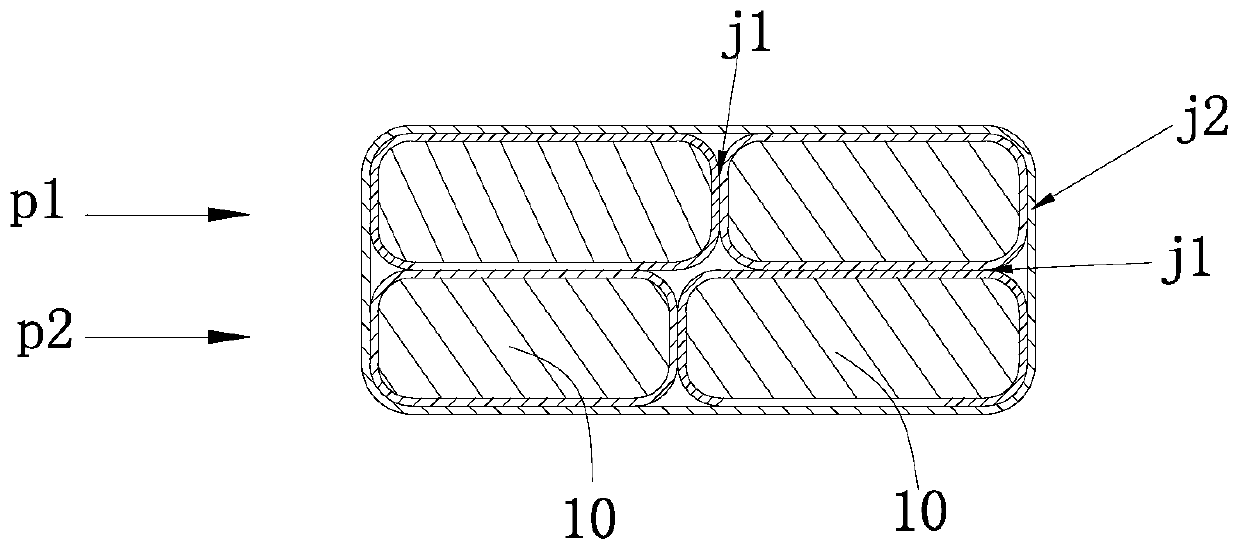
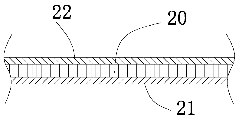
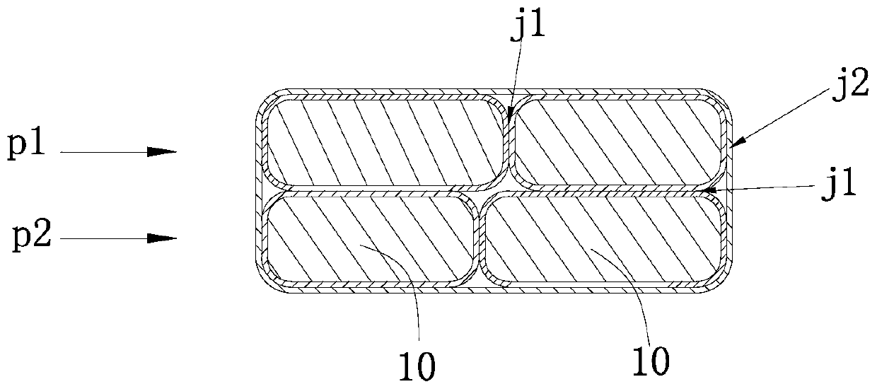
[0021] Such as figure 1 , figure 2 As shown, a magnet wire for a high-power wind power generator includes a conductor 10 and an insulating layer attached to the outside of the conductor 10. There are four conductors 10, and the four conductors 10 are arranged and arranged close together. The four conductors 10 are arranged and formed There are the first row p1 and the second row p2, the cross-sectional shape of the four conductors 10 arranged close together is rectangular, the widths of the two conductors 10 in the first row p1 are not equal, and the widths of the two conductors 10 in the second row p2 The width values ​​of the conductors 10 are not equal, and the total width value of the two conductors 10 in the first row p1 is equal to the total width value of the two conductors 10 in the second row p2. The width...


PUM

PropertyMeasurementUnit
thicknessaaaaaaaaaa
widthaaaaaaaaaa
thicknessaaaaaaaaaa

Abstract

The invention relates to an electromagnetic wire for a high-power wind driven generator. The electromagnetic wire comprises conductors and insulation layers attached at the outer portions of the conductors, the plurality of conductors are arranged and close to each other, the sections of the conductors arranged close to each other are rectangular, and the insulation layers comprise first insulation layers attached to the conductors and second insulation layers binding the conductors and attached to the outer sides of the first insulation layers. The electromagnetic wire for the high-power winddriven generator replaces a large-specification conductor with the plurality of small-specification conductors in the prior art, so that the overall strength and hardness of the electromagnetic wireare reduced, the electromagnetic wire is easy to machine and form, the drawn electromagnetic coil is regular and attractive in shape, the electromagnetic wire is not easy to damage in the forming process, the phenomenon that an insulating layer is lost due to deformation of the electromagnetic wire during processing is avoided, and a foundation is provided for thinning design of the insulating layers.

Description

technical field [0001] The invention belongs to the technical field of special winding wires, and in particular relates to an electromagnetic wire product suitable for high-power wind power generators. Background technique [0002] Electromagnetic wire products are mainly used in the stator coils of high-power 7MW and above direct-drive wind turbines. The size specifications of the electromagnetic wires used in the prior art are usually 4mm×16mm and above. When winding into shuttle coils, the size is usually 11 to 12 Turns of a single electromagnetic wire are stacked together. Since the larger the specification of a single electromagnetic wire, the higher its strength and hardness, it takes a lot of force to draw it into a frame-shaped coil. The requirements for drawing equipment are very high. At the same time, the shape of the drawn coil is not regular and perfect. It is difficult to correct the shape in the subsequent baking process, and the electromagnetic wire is easily...

Claims


Application Information

Patent Timeline
Patent Type & Authority Applications(China)
IPC IPC(8): H01B7/02H01B7/08H02K3/04H02K3/32H02K3/34
CPCH01B7/0216H01B7/08H02K3/04H02K3/32H02K3/34H02K2213/03
Inventor 郑一帆顾新梅
Owner SUZHOU GUANLONG MAGNET WIRE
Learn More