High-speed direct current switch reluctance generator converter system

A reluctance generator and DC switch technology, which is applied in the direction of controlling the generator through the change of the magnetic field, controlling the generator, and controlling the system, can solve the problems of not maximizing the benefit, complicated regulation mode, and large switching loss, etc., and achieves Effects with simple structure, strong scalability and simple control

Active Publication Date: 2019-07-12
CHINA JILIANG UNIV
View PDF6 Cites 0 Cited by
  • Summary
  • Abstract
  • Description
  • Claims
  • Application Information

AI Technical Summary

Problems solved by technology

[0003] For the current conversion systems of various types of switched reluctance generators, the conversion mode and the conversion circuit of each phase winding of a switched reluctance generator are the same, and the conversion control mode of each phase winding is also the same, but In some demanding occasions, the control mode is complicated, so the windings of each phase adopt the same structure and control, so the overall control complexity is caused, and the switching loss is also large.
[0004] Moreover, in the current conversion mode of each phase winding of the existing switched reluctance generator, the work of

Method used


Image

  • High-speed direct current switch reluctance generator converter system
  • High-speed direct current switch reluctance generator converter system

Examples


Embodiment Construction

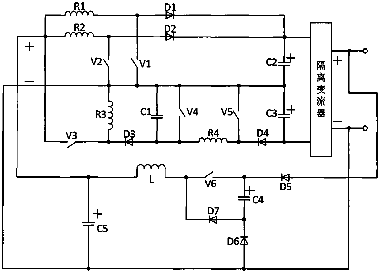
[0025]The high-speed DC switched reluctance generator converter system of this embodiment consists of a first phase winding R1, a second phase winding R2, a third phase winding R3, a fourth phase winding R4, a first switching tube V1, and a second switching tube V2 , the third switch tube V3, the fourth switch tube V4, the fifth switch tube V5, the sixth switch tube V6, the first diode D1, the second diode D2, the third diode D3, the fourth diode Tube D4, fifth diode D5, sixth diode D6, seventh diode D7, first capacitor C1, second capacitor C2, third capacitor C3, fourth capacitor C4, fifth capacitor C5, inductor L. Composed of an isolated converter, one end of the first phase winding R1 is connected to one end of the second phase winding R2, and connected to the anode of the third switching tube V3, the positive pole of the fifth capacitor C5, and one end of the inductor L, and the other end of the first phase winding R1 It is connected to the anode of the first switching tub...


PUM


Abstract

The invention relates to a high-speed direct current switch reluctance generator converter system. The system comprises four-phase windings, six switch tubes, seven diodes, five capacitors, an inductor and an isolation converter. Converter loops of the first phase winding and the second phase winding have simple structures and the same control modes, and a third phase winding and a fourth phase winding are asymmetrically integrated conversion structures. By depending on the relatively complex converter loops and the regulation and control of the fourth phase winding, the measure of enhancementof the power generation capacity of the fourth phase winding itself can be achieve such as a follow current stage, and the fourth phase winding can be mutually promoted with the third phase winding to indirectly improve the power generation capacity of the first phase winding and the second phase winding; and besides, the structure is high in expandability, the output end is connected in series to increase the voltage, the total excitation source of each phase winding is regulated according to the duty ratio of a sixth switch tube so that the high-speed direct current switch reluctance generator converter system is a set of high-performance conversion system, is especially suitable for the high-speed direct current switch reluctance generator application field, and can be taken as one ofthe generator in the internal direct current microgrid in a full-electric aircraft.

Description

technical field [0001] The invention relates to the field of switched reluctance generator systems, in particular to a converter system of a high-speed switched reluctance generator, especially the structure and control method of its converter main circuit. Background technique [0002] At present, in the application field of switched reluctance generators, high-speed switched reluctance generators, especially in the aviation field, have been relatively maturely applied, and the general speed is 8,000 rpm to 100,000 rpm. With the development, the converter system of high-speed switched reluctance generator has also been developed. [0003] For the current conversion systems of various types of switched reluctance generators, the conversion mode and the conversion circuit of each phase winding of a switched reluctance generator are the same, and the conversion control mode of each phase winding is also the same, but In some occasions with high requirements, the control mode ...

Claims


Application Information

Patent Timeline
IPC IPC(8): H02P9/00H02P9/30
CPCH02P9/00H02P9/30
Inventor 孙冠群
Owner CHINA JILIANG UNIV
Why Eureka
Try Eureka