Oscillator arrangement and method for synchronizing an oscillator

An oscillator and synchronizer technology, which is applied to power oscillators, synchronizing devices, automatic power control, etc., and can solve problems such as the inability of PLL to work

Pending Publication Date: 2019-07-12
INFINEON TECH AG
View PDF0 Cites 0 Cited by
  • Summary
  • Abstract
  • Description
  • Claims
  • Application Information

AI Technical Summary

Problems solved by technology

In extreme cases like this...

Method used


Image

  • Oscillator arrangement and method for synchronizing an oscillator
  • Oscillator arrangement and method for synchronizing an oscillator
  • Oscillator arrangement and method for synchronizing an oscillator

Examples


Embodiment Construction

[0020] The following detailed description refers to the accompanying drawings, which illustrate, by way of illustration, specific details and aspects of the present disclosure in which the present invention can be practiced. Other aspects can be used, and structural, logical, and electrical changes can be made without departing from the scope of the invention. The various aspects of the present disclosure are not necessarily mutually exclusive, because some aspects of the present disclosure may be combined with one or more other aspects of the present disclosure to form new aspects.

[0021] If phase lock is only required when a reference signal (ie, a synchronization signal) is available, a synchronized oscillator is a standard solution that provides almost instant lock.

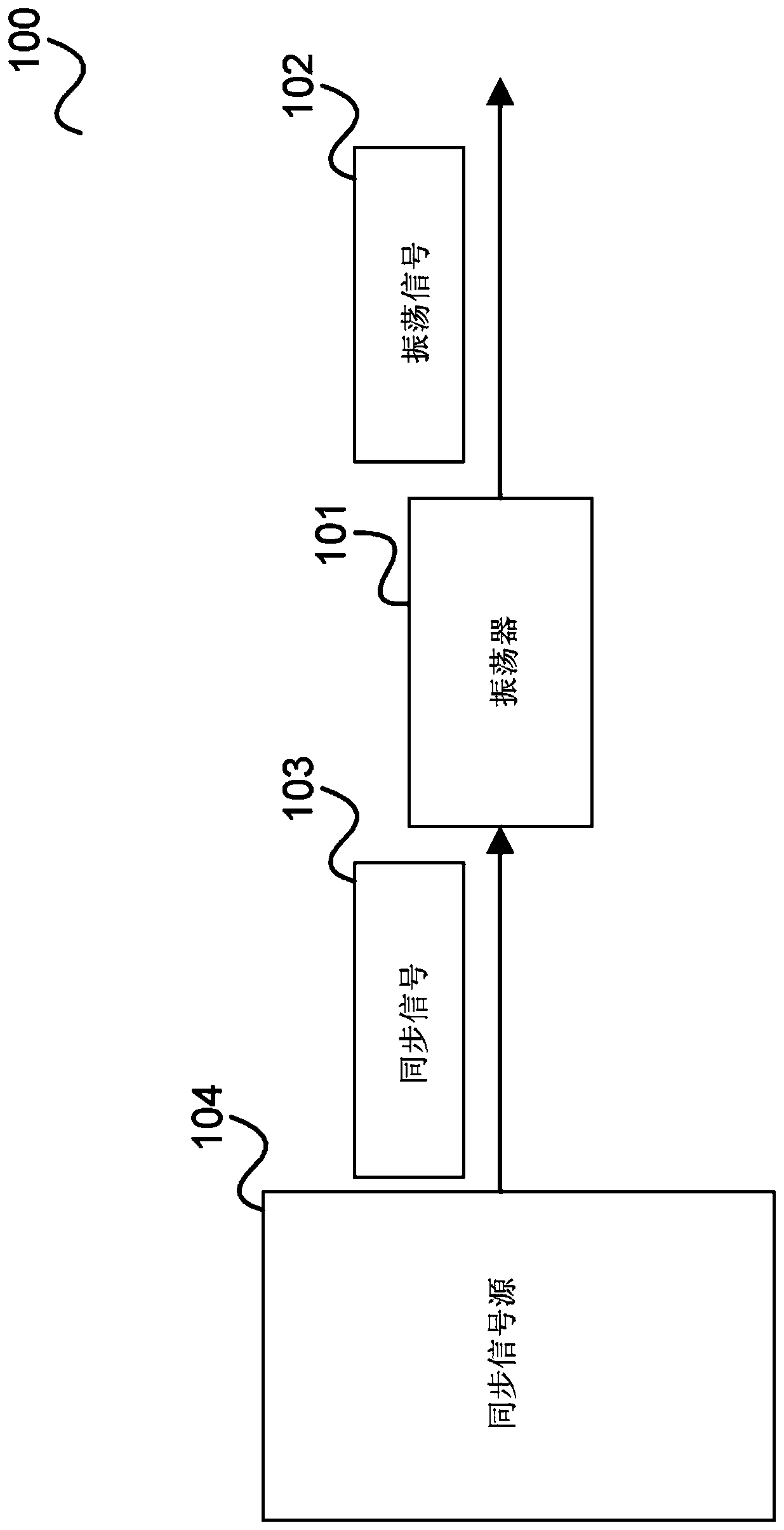
[0022] figure 1 The oscillator device 100 is shown.

[0023] The oscillator device 100 includes an oscillator 101 that generates an oscillation signal 102. The oscillating signal 102 has two alternating half-per...


PUM


Abstract

The invention discloses an oscillator arrangement and method for synchronizing an oscillator. The oscillator arrangement having an oscillator configured to generate an oscillation signal having two half-cycles, an input configured to receive a synchronization signal including synchronization triggers, a synchronizer configured to reject a synchronization trigger received during a first part of a half-cycle and to synchronize the oscillator to a synchronization trigger received during a second part of the half-cycle, and a controller configured to prolong the second part of the half-cycle in response to receiving a synchronization trigger during the first part of the half-cycle.

Description

Technical field [0001] The present disclosure relates to oscillator devices and methods for synchronizing oscillators. Background technique [0002] Phase-locked loop (PLL) devices are generally used in applications where a periodic signal that must be synchronized with a reference signal must be generated. The PLL consists of a variable frequency oscillator in which the frequency is adjusted by means of phase comparison to lock on the phase of the reference signal. Depending on both the phase and frequency difference between the PLL oscillator and the reference signal, the phase locking operation may take several cycles. Therefore, if the reference signal is not continuously available, but appears from time to time and even for several cycles, the phase locking operation becomes a problem. In fact, in this case, the possibly considerable phase error should be corrected in a few cycles. The application scenario is even worse when the reference voltage may disappear while remai...

Claims


Application Information

Patent Timeline
IPC IPC(8): H03L7/099
CPCH03L7/099H03L7/00H03B5/18H03K3/84H03K5/00H03K5/01H03K17/00H03L7/0991H03L7/104H04L7/0331
Inventor 马尔科·布奇雷蒙多·卢齐
Owner INFINEON TECH AG
Why Eureka
Try Eureka