
Frequency measuring and control apparatus with integrated parallel synchronized oscillators

a technology of parallel synchronized oscillators and frequency measuring and control apparatus, which is applied in the direction of scanning probe techniques, frequency to phase shift conversion, instruments, etc., can solve the problems of inability to run cantilever excitation and pll detection at harmonic frequencies, inability to handle constant frequency changes very well, and considerable cost of configuration for each additional lock-in

Inactive Publication Date: 2015-04-09
RHK TECH
View PDF4 Cites 1 Cited by
  • Summary
  • Abstract
  • Description
  • Claims
  • Application Information

AI Technical Summary

Benefits of technology

The patent describes a device that has multiple oscillators that work together to measure and control frequency. This device is designed to be programmable, meaning it can be customized easily to perform different tasks.

Problems solved by technology

But the disadvantage of this configuration is that it is not possible to run cantilever excitation and PLL detection at harmonic frequencies of each other.
But such a configuration is considerably costly for each additional lock-in, and runs on an external reference.
Modern digital lock-ins generate the reference using a PLL with very low time constant and, thus, cannot handle constant changes in frequency very well.
In any event, it is not possible with such a configuration to provide a fixed offset from the fluctuating PLL reference frequency or a harmonic thereof.
But this design does not permit setting up the two DDS chips with different frequencies as is required for detecting or exciting relatively high harmonics.
Finally, with analog PLL circuits, although it is possible to create integer and fractional multiples of a base frequency with frequency dividers between a VCO and a mixer, it is complicated to build a variable frequency ratio frequency multiplier this way and it is impossible to have the circuit output pure sine waves this way.

Method used


Image

  • Frequency measuring and control apparatus with integrated parallel synchronized oscillators
  • Frequency measuring and control apparatus with integrated parallel synchronized oscillators
  • Frequency measuring and control apparatus with integrated parallel synchronized oscillators

Examples


Embodiment Construction

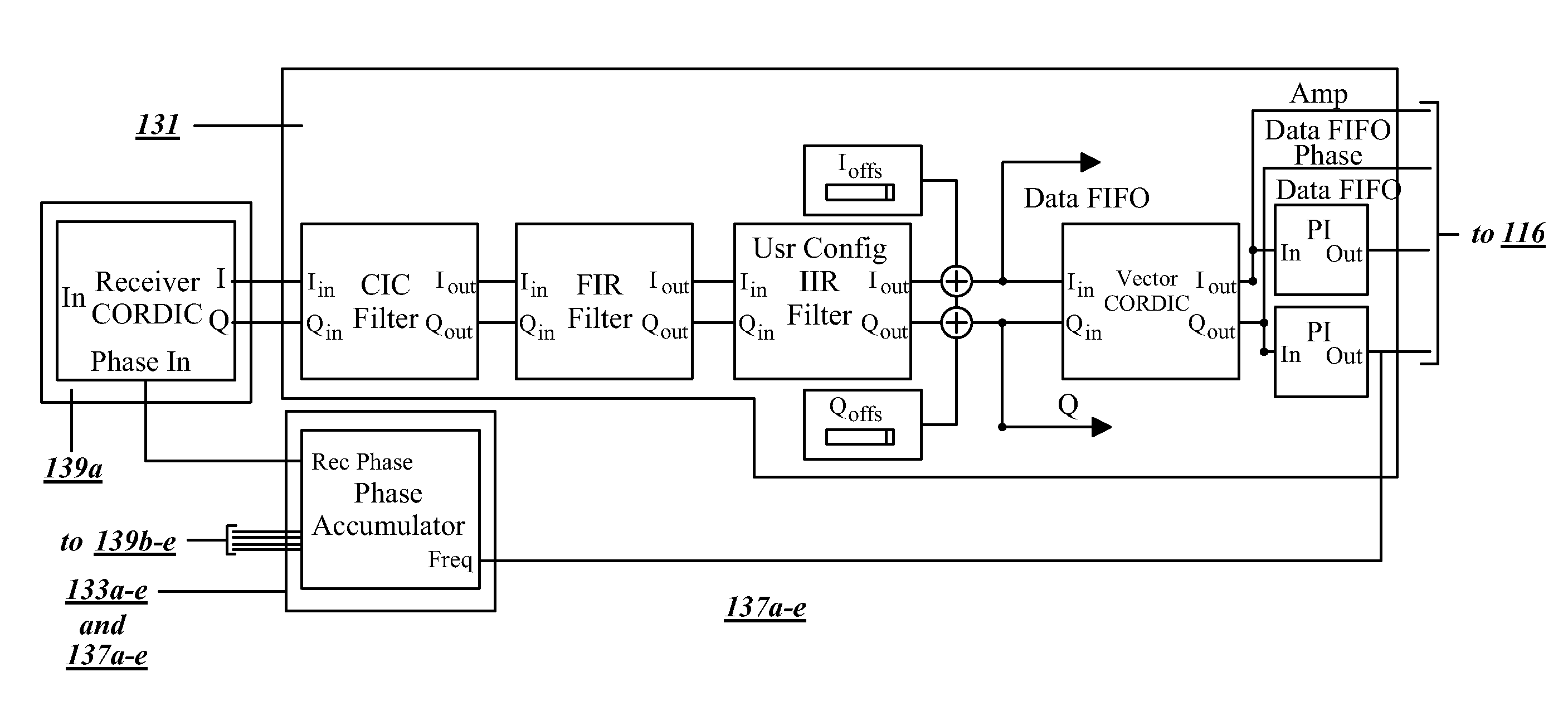
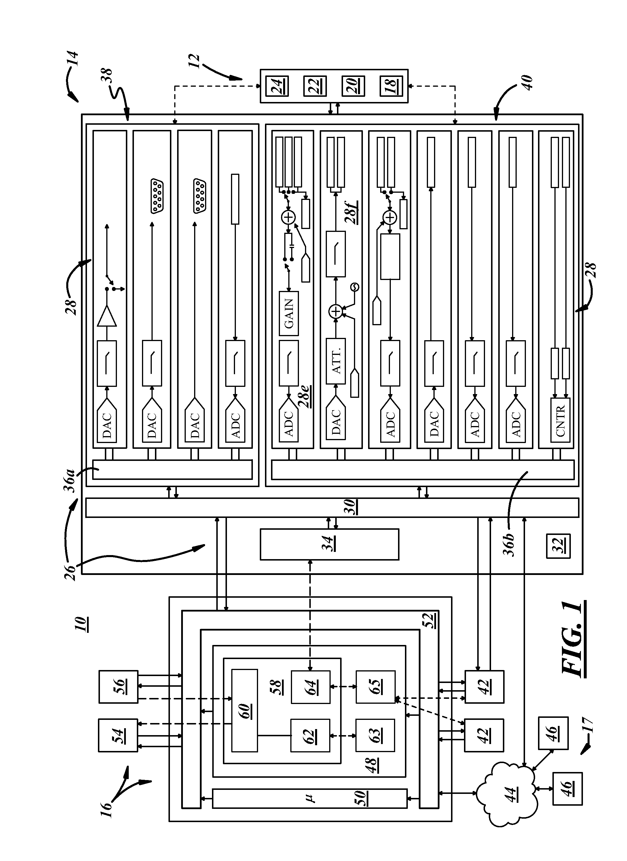
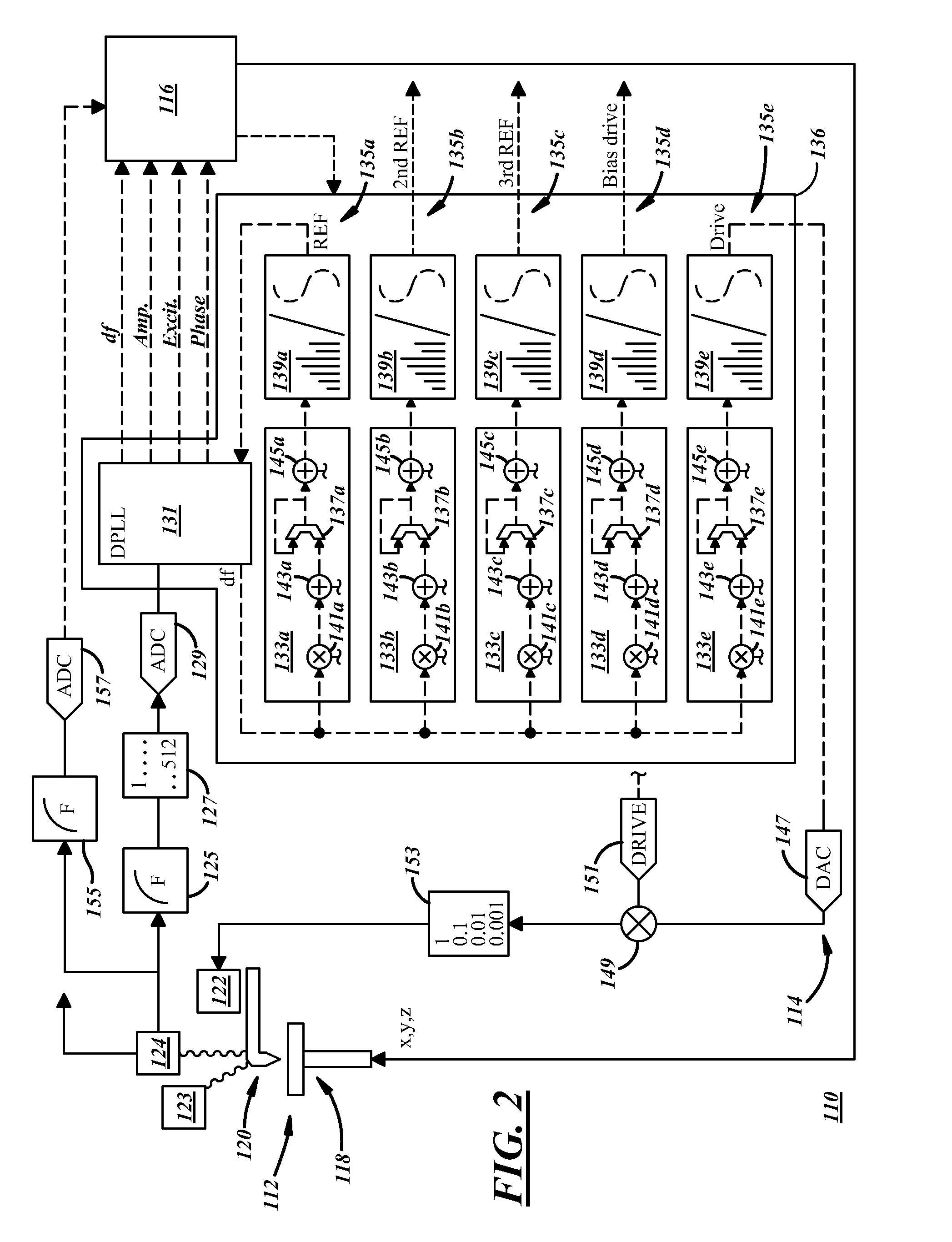
[0011]In general, an electronic frequency measuring and controlling apparatus will be described using one or more examples of illustrative embodiments of multiple synchronized oscillators. The example embodiment(s) will be described with reference to its use in an SPM environment. However, it will be appreciated as the description proceeds that the invention is useful in many different applications and may be implemented in many other embodiments. In this regard, and as used herein and in the claims, it will be understood that the term “system” refers not only to SPM applications, but also to any other suitable applications.

[0012]Referring specifically to the drawings, FIG. 1 illustrates an illustrative embodiment of an SPM system 10, which generally may include probe equipment 12 to interact with a material of interest, electronic instrumentation 14 to interact with the probe equipment 12, a computer 16 to interact between the instrumentation 14 and a user, and system peripherals 1...


PUM


Abstract

A frequency measuring and control apparatus includes a plurality of synchronized oscillators integrated in parallel into one programmable logic device.

Description

CROSS-REFERENCE TO RELATED APPLICATION[0001]This present application claims priority from U.S. patent application Ser. No. 13 / 583,952 filed on Sep. 11, 2012, PCT Patent Application PCT / US2011 / 28859 filed on Mar. 17, 2011, and U.S. Provisional Patent Application No. 61 / 315,823 filed Mar. 19, 2010, all of which are incorporated herein by reference in their entireties.TECHNICAL FIELD[0002]This disclosure relates generally to frequency measuring and control and, more particularly, to frequency control with phase locking.BACKGROUND[0003]Many technologies employ phase locked loops (PLLs). For example, in scanning probe microscopy, scientists use scanning probe microscopes (SPMs) to reveal data about various properties of materials, like gold or silicon, at very fine resolution down to molecules and atoms of the materials. SPMs are a family of ultra-high magnification instruments that include Scanning Tunneling Microscopes (STMs), Atomic Force Microscopes (AFMs), Near Field Scanning Optica...

Claims


Application Information

Patent Timeline
Patent Type & Authority Applications(United States)
IPC IPC(8): H03L7/099G01Q30/00G01R23/02H03L7/085
CPCH03L7/0991G01R23/02G01Q30/00H03L7/085B82Y35/00H03L7/0805H03L2207/50H03L7/099G01Q10/065G01Q10/06G01R23/06G01Q30/04G01R23/155G01R23/12
Inventor PORTHUN, STEFFEN
Owner RHK TECH
Learn More