Gravity self-centering self-locking clamp

A self-centering and self-locking clip technology, applied in the field of machining, can solve the problems of increasing the scrap rate, strong dependence, easy to crush the workpiece, etc., and achieve the effect of strengthening the connection firmness, strong versatility, and easy clamping.

Pending Publication Date: 2019-07-16
徐旭东
View PDF1 Cites 13 Cited by
  • Summary
  • Abstract
  • Description
  • Claims
  • Application Information

AI Technical Summary

Problems solved by technology

On the conveyor belt, if there is no fixture to fix the parts when they are processed, it is easy to produce products with unqualified processing dimensions and increase the scrap rate
Therefore, the parts to be processed are usually manually pressed to avoid the movement of the parts, but this manual operation of pressing the parts not only increases the labor intensity of the workers, but also the force of pressing the parts is not easy to control
[0004] Patent CN109318137A discloses a positioning device for automatic assembly line, including: at least three sets of fixed flatness determination components; jacking unlocking mechanism, the jacking unlocking mechanism is arranged directly below the flatness determining component, wherein the jacking The lifting and unlocking mechanism includes: a jacking assembly; and an unlocking assembly, the unlocking assembly is arranged directly above the jacking assembly, the upper surface of the unlocking assembly is provided with a positioning fixture, the unlocking assembly is supported by the jacking assembly and placed on the jacking assembly Driven by the drive, it can be selectively raised and lowered in the vertical direction, so that the positioning fixture can be selectively lifted to the lower surface of the flatness determination component; this technical solution improves the response speed of the lifting and unlocking action while improving the degree of automation. This further improves the matching degree between the jacking and unlocking action and the subsequent positioning action, but it uses a combination of motor and gear set, and a controller needs to be added in the later stage. The cost is high, the structure is complicated, and the maintenance professional requirements are high, relying on the controller To improve the accuracy, the system is more complex, highly dependent on electricity, and consumes energy; in addition, this technical solution uses elastic materials (briquetting blocks) and non-elastic materials to compress stable and beating parts, relying on the small deformation of the material itself, Easy to crush the workpiece

Method used


Image

  • Gravity self-centering self-locking clamp
  • Gravity self-centering self-locking clamp
  • Gravity self-centering self-locking clamp

Examples


Embodiment Construction

[0031] The present invention will be further described in conjunction with the accompanying drawings and specific embodiments.

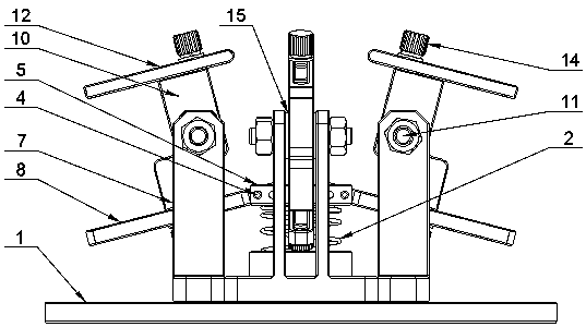
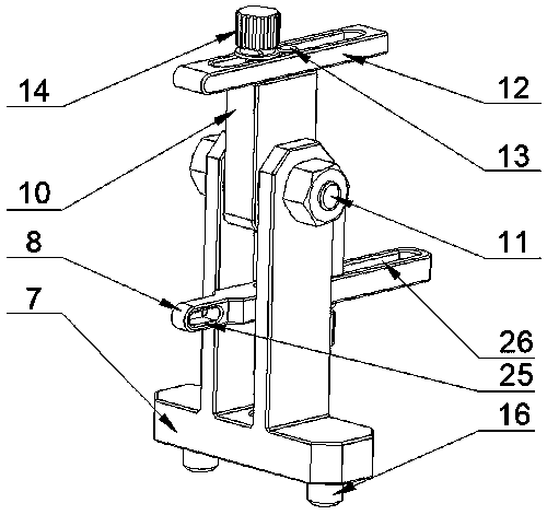
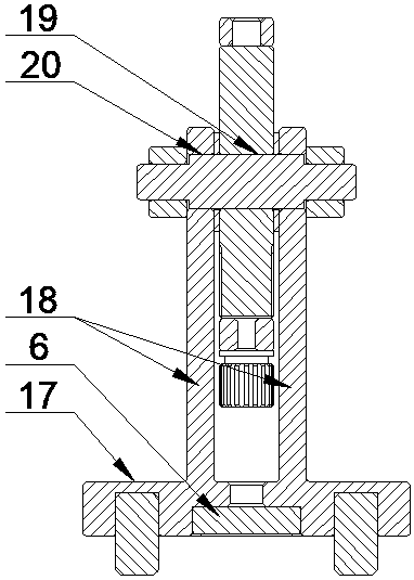
[0032] Such as Figure 1~Figure 5 As shown, the present invention discloses a gravity self-centering self-locking fixture, which is composed of a chassis 1, a load-bearing structure and four clamping units, the chassis 1 is cylindrical, and the clamping unit is movably fixed on the chassis around the load-bearing structure 1, the distance between the clamping units is equal and the distance to the bearing structure is also equal. The clamping unit is composed of clamping rod 12, lifting rod 8, clamping arm 10 and column 7, and the column 7 is supported by support rod I17 and two supports Two support rods II18 are fixed on the support rod I17 in parallel and vertically. A circular through hole I19 is provided in the middle of the clamp arm 10, and a circular through hole II20 is provided on each of the two support rods II18. The through hole I19 and ...


PUM


Abstract

The invention discloses a gravity self-centering self-locking clamp. The gravity self-centering self-locking clamp is composed of a chassis, a bearing structure and two or more clamping units. Each clamping unit is composed of a clamping rod, a lifting rod, a clamping arm and a stand column. The stand columns and chassis are fixed. The clamping arms are fixed on the stand columns and can rotate along the stand columns. The clamping rods are fixed at the top ends of the clamping arms. The lifting rods are fixed at the bottom ends of the clamping arms. The bearing structure is composed of a spring and a carrier plate. The spring makes contact with the chassis. The carrier plate is fixedly connected with the lifting rod. The modular design is adopted, gravity and elastic force are combined through the lever principle, products are automatically clamped when being placed in the clamp and automatically loosened when being taken out from the clamp, and the clamp has the automatic centering effect and the self-locking effect.

Description

technical field [0001] The invention belongs to the technical field of mechanical processing, and in particular relates to a gravity self-centering and self-locking fixture on a production line. Background technique [0002] Fixture is a commonly used tool in the process of machining. It is a device used to fix the processing object in the process of mechanical manufacturing so that it can occupy the correct position for construction or inspection. It is used to fix the material or part to be processed, to ensure that it will not move and shift during the processing, and to avoid the deviation of the object to be processed from affecting the precision and accuracy of the processing operation. In a broad sense, in any process of the processing process, the device used to quickly, conveniently and safely install the workpiece can be called a fixture, such as welding fixtures, inspection fixtures, assembly fixtures, machine tool fixtures, etc. [0003] In order to improve prod...

Claims


Application Information

Patent Timeline
Patent Type & Authority Applications(China)
IPC IPC(8): B23Q3/06
CPCB23Q3/06
Inventor 徐旭东陈扬
Owner 徐旭东
Why Eureka
Try Eureka