
Rail transit traction system based on flux-switching permanent magnet linear motor

A magnetic flux switching and linear motor technology, applied in the field of train systems, can solve the problems of reducing motor operation reliability, noise, and limiting applications

Pending Publication Date: 2019-07-16
NANJING UNIV OF AERONAUTICS & ASTRONAUTICS
View PDF5 Cites 3 Cited by
  • Summary
  • Abstract
  • Description
  • Claims
  • Application Information

AI Technical Summary

Problems solved by technology

However, when this type of motor is used in the rail transit field, the traction force fluctuates greatly, which will cause obvious noise and reduce the reliability of the motor operation, which limits the application of this type of motor in the rail transit field

Method used


Image

  • Rail transit traction system based on flux-switching permanent magnet linear motor
  • Rail transit traction system based on flux-switching permanent magnet linear motor
  • Rail transit traction system based on flux-switching permanent magnet linear motor

Examples


Embodiment 1

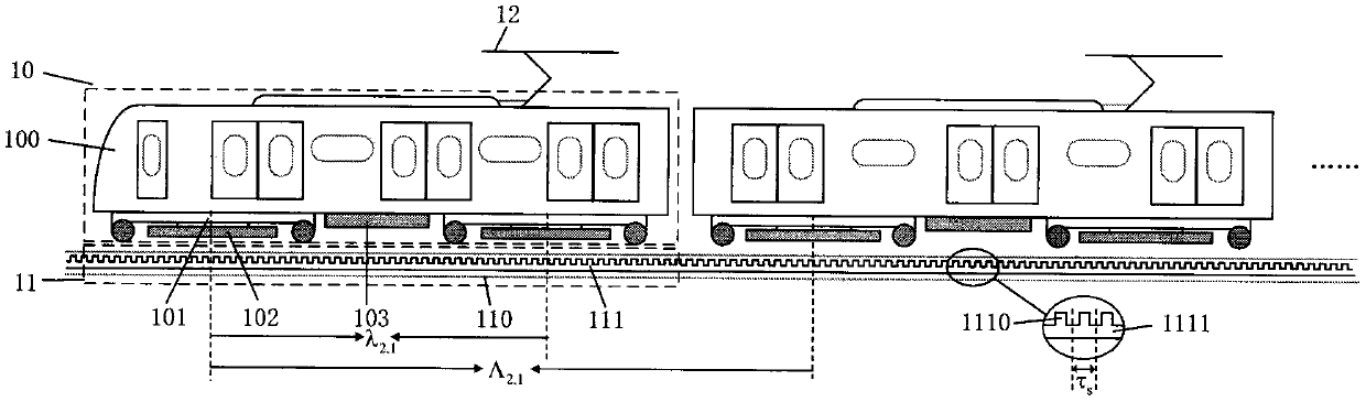
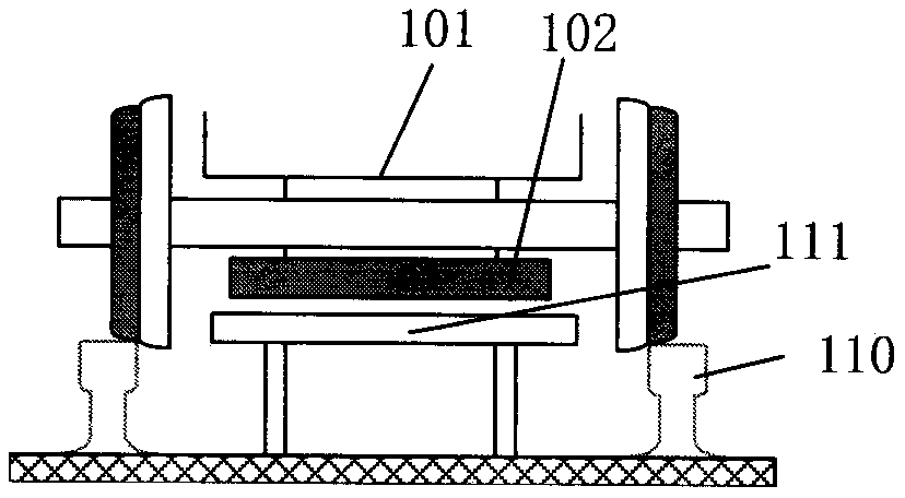
[0058] see figure 1 , figure 1 It is a rail transit traction system based on permanent magnet flux switching linear motors of the present invention. In this embodiment, there are 4 subsystems of urban rail transit traction systems based on permanent magnet flux switching linear motors. Since the motors in each subsystem The spatial distribution method is the same, and the subsystems of the train are distributed equidistantly in the space, so figure 1 Only the first two of them are shown in . In order to show the various parts in this embodiment more clearly, figure 1 Enlarging the compartment 10 increases the distance between the rails 11. In actual situations, the two are in close contact through the wheel rails, such as figure 2 shown.

[0059] In this embodiment, i=1, p=1, j=4, q=0. In this embodiment, the subsystem of the urban rail transit traction system based on the permanent magnet flux switching linear motor includes a carriage 10, a track 11 and a DC power supp...

Embodiment 2

[0078] see Figure 5 , Figure 5 It is a rail transit traction system based on a permanent magnet flux switching linear motor of the present invention. The difference between this embodiment and Embodiment 1 is that the number of motors is increased in this embodiment to achieve the purpose of reducing more orders of traction harmonics. Since the spatial distribution of motors in each subsystem is the same, and each subsystem is equally spaced in space, so Figure 5 Only the first two subsystems are shown in .

[0079] In this embodiment, i=1, p=2, j=2, q=1. That is, each car 10 includes a car body 100, a bogie 101, i*2 p = Primary 102 of 4 permanent magnet flux switching linear motors. j*2 q = Four subsystems of urban rail transit traction system based on permanent magnet flux switching linear motor form a complete traction system. It is the number of the subsystem, which is respectively marked as S1, S2, S3, and S4 from left to right; it is the number of the motor in ...


PUM


Abstract

The invention discloses a rail transit traction system based on a flux-switchingpermanent magnet linear motor. The rail transit traction system based on theflux-switching permanent magnet linear motoris composed of several subsystems;the subsystems of the urban rail transit traction system based on the flux-switching permanent magnet linear motor comprise a carriage, a rail, and a direct currentpower supply system;the carriage comprises a carriage main body, a bogie, i*2of primaries of the flux-switching permanent magnet linear motor, and an inverter and motor controller;the rail comprises a train guide rail and a secondary of the flux-switchingpermanent magnet linear motor;and the j*2<q> of the subsystems of the urban rail transit traction system based on the flux-switching permanentmagnet linear motor constitute a complete traction system. The rail transit traction system based on the flux-switching permanent magnet linear motor has the characteristics of being simple in secondary structure, high in system efficiency,and high in system power factor, a setting rule of space distance of the primaries of the flux-switching permanent magnet linear motor in the traction system is proposed, the fluctuation ofsystem traction force can be effectively reduced, noise during train operation is further reduced, and stability is improved.

Description

technical field [0001] The invention relates to a train system driven by a permanent magnet flux switching linear motor, belonging to the technical field of motor drive and control. Background technique [0002] In the process of urbanization, rail transit plays an indispensable role. Trains driven by traditional rotating motors need to rely on mechanical transmissions to convert rotational torque into adhesive traction, resulting in low efficiency, and the output traction is affected by factors such as track conditions and friction coefficients, so the climbing ability and turning ability are poor. The route planning is inconvenient, the cost is high, and its application is limited. Compared with the rotary motor, the linear motor drive system directly generates electromagnetic force, which is a non-adhesive traction force, which gets rid of the influence of the track condition. At the same time, the linear motor does not need a mechanical transmission device, so it has th...

Claims


Application Information

Patent Timeline
Patent Type & Authority Applications(China)
IPC IPC(8): B60L13/03
CPCB60L13/03B60L2200/26Y02T10/72
Inventor 曹瑞武陆鸣航苏恩超
Owner NANJING UNIV OF AERONAUTICS & ASTRONAUTICS
Learn More