

A charging pile and charging method
A charging pile and voltage technology, used in charging stations, electric vehicle charging technology, electric vehicles, etc., can solve the problems of large output current, low performance index, complex control, etc., and achieve the effect of wide output voltage range and constant power output
- Summary
- Abstract
- Description
- Claims
- Application Information
AI Technical Summary
Problems solved by technology
Method used
Image

Examples
Embodiment 1
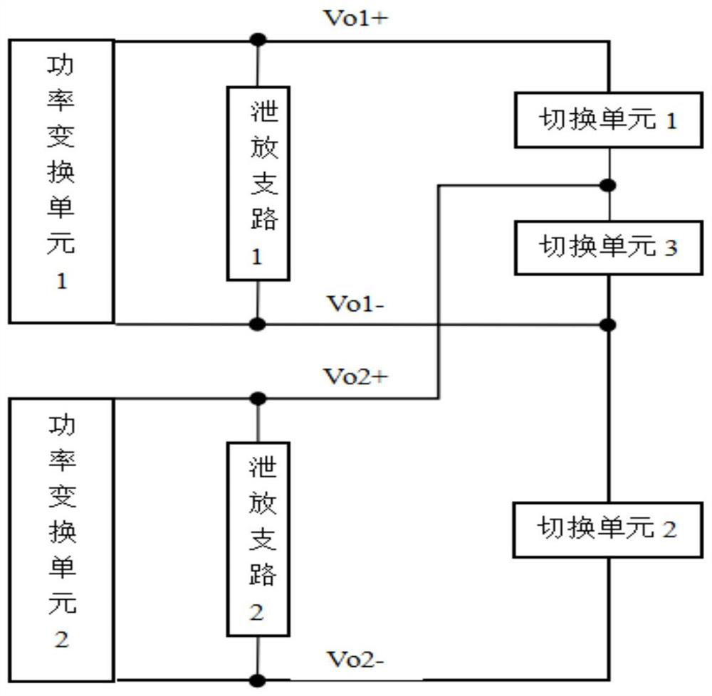
[0030] figure 1 It is a schematic structural diagram of a charging pile provided in Embodiment 1 of the present invention. Such as figure 1 As shown, the charging pile includes:
[0031] A power conversion unit for outputting independent voltages, the power conversion unit includes a power conversion unit 1 and a power conversion unit 2, the power conversion unit 1 outputs independent voltages Vo1+, Vo1-, and the power conversion unit 2 outputs an independent voltage Vo2+ , Vo2-;
[0032] A switching unit for switching, the switching unit includes a switching unit 1, a switching unit 2 and a switching unit 3; the switching unit 1 is connected in parallel at the positive output terminal of the power conversion unit 1, the Vo1+ and the power conversion Between the Vo2+ of the positive output terminal of the unit 2, the switching unit 2 is connected in parallel between the Vo1- of the negative output terminal of the power conversion unit 1 and the Vo2- of the negative output t...
Embodiment 2
[0048] Embodiment 2 of the present invention provides a charging method applied to the charging pile provided in Embodiment 1. The charging method includes:
[0049] When the switching unit 3 is turned off, the switching units 1 and 2 are turned on, the positive output terminal Vo1+ and the positive output terminal Vo2+ are connected together through the switching unit 1, and the negative output terminal Vo1- and the negative output terminal Vo2- are connected through the The switching unit 2 is connected together, the power conversion unit 1 and the power conversion unit 2 are connected in parallel, the total output voltage of the charging pile is equal to each independent output voltage, and the total output current is equal to the sum of each independent output current .
[0050] Wherein, the method also includes:
[0051] When the switching unit 3 is turned on, the switching units 1 and 2 are turned off, the positive output terminal Vo2+ and the negative output terminal V...
Embodiment 3
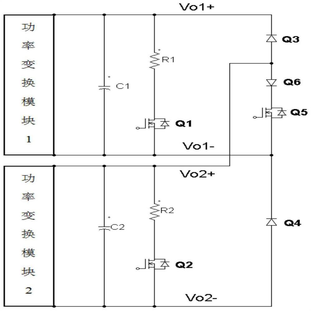
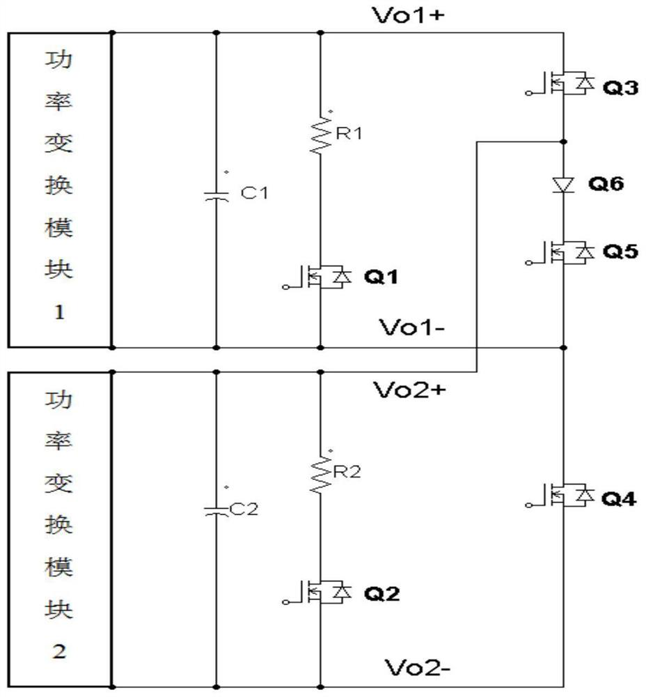
[0055] figure 2 It is a schematic structural diagram of the charging pile provided in Embodiment 3 of the present invention, image 3 It is a schematic structural diagram of another charging pile provided in Embodiment 3 of the present invention.
[0056] In Embodiment 3 of the present invention, the power conversion unit includes but is not limited to an input source, an LLC resonant conversion circuit and a rectifier circuit. The topology of the LLC resonant conversion circuit series includes ordinary half-bridge, clamped diode half-bridge, and full-bridge , Three-phase half-bridge type, etc.; the rectifier circuit can use a full-bridge rectifier circuit or a full-wave rectifier circuit.
[0057] In the third embodiment of the present invention, the switching unit includes but is not limited to a switching device or a diode, and the switching unit 1 and the switching unit 2 can be full-controlled or half-controlled semiconductor switching devices ( image 3 ), or a low fr...
PUM
 Abstract
Description
Claims
Application Information