Self-locking centrifugal compressor impeller structure
A centrifugal compressor and self-locking technology, which is applied in the direction of mechanical equipment, non-variable pumps, machines/engines, etc., can solve the problems of low connection reliability, improve dynamic balance accuracy, increase friction, and improve The effect of maximum torque
- Summary
- Abstract
- Description
- Claims
- Application Information
AI Technical Summary
Problems solved by technology
Method used
Image

Examples
Embodiment 1
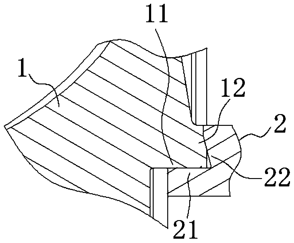
[0042] A self-locking centrifugal compressor impeller structure, such as figure 1 and figure 2 As shown, the impeller 1 and the rotor shaft 2 are included. Such as figure 2 As shown, an inner spigot 11 is provided on the end surface of the impeller 1 , and an outer tapered surface 12 is provided on a surface perpendicular to the inner spigot 11 . An outer spigot 21 is provided on the end surface of the rotor shaft 2 , and an inner tapered surface 22 is provided on a surface perpendicular to the outer spigot 21 . The outer spigot 21 is transition fit or interference fit in the inner spigot 11 , and at the same time, the outer conical surface 12 is in contact with the inner conical surface 22 , so that the impeller 1 is connected to the rotor shaft 2 . It is worth noting that: the angle between the outer cone surface 12 and the inner cone surface 22 relative to the horizontal direction is 50° to 80°. Considering the strength of the material of the impeller 1 and the rotor s...
Embodiment 2
[0046] As preferably, in order to realize the present invention better, optimize further on the basis of above-mentioned embodiment, especially adopt following setting structure:
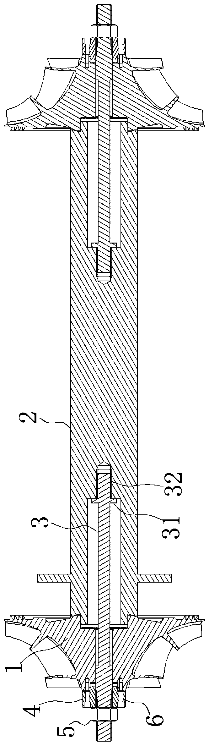
[0047] Such as Figure 1 to Figure 5 As shown, the interior of the rotor shaft 2 has a cavity, and a tie rod 3 is arranged between the impeller 1 and the rotor shaft 2, and the tie rod 3 is arranged in the cavity. A threaded hole 32 is provided at the axial center of the cavity of the rotor shaft 2 , the end of the pull rod 3 has an external thread, and the pull rod 3 is threadedly connected to the threaded hole 32 through the external thread. Wherein, the screw thread direction of the screw hole 32 is opposite to the rotation direction of the impeller 1 . The pull rod 3 is provided with a limiting boss 31 at a position close to the external thread. A locking nut 5 is arranged on the tie rod 3 for locking the impeller 1 on the rotor shaft 2 .
[0048]The screw thread direction of the threaded hol...
Embodiment 3
[0050] As preferably, in order to realize the present invention better, optimize further on the basis of above-mentioned embodiment, especially adopt following setting structure:
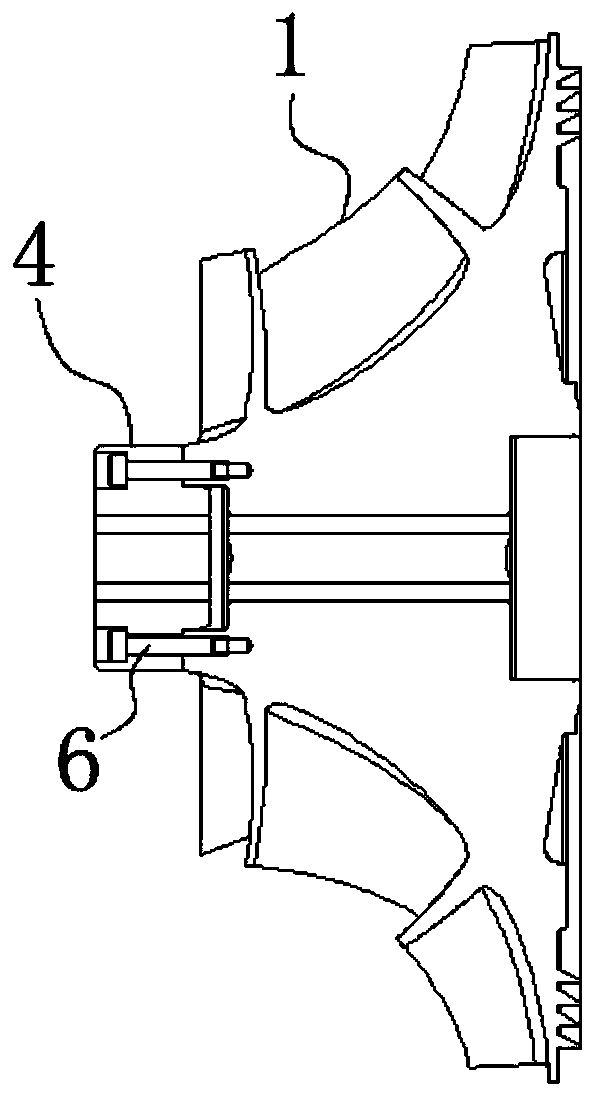
[0051] Such as Figure 1 to Figure 5 As shown, an impeller gasket 4 is arranged between the lock nut 5 and the impeller 1, and the impeller gasket 4 and the end surface of the impeller 1 are connected by a key. A screw hole 41 is provided on the impeller spacer 4 , and the impeller spacer 4 is fixedly connected with the impeller 1 through the screw hole 41 by the screw 6 . To ensure that the relative rotation between the impeller spacer 4 and the impeller 1 does not occur.
[0052] Such as Figure 1 to Figure 5 As shown, the pull rod 3 is also provided with a square key 7, and the center of the impeller 1 and the impeller gasket 4 is provided with a square hole that fits with the square key 7. The impeller 1 and the impeller gasket 4 are connected to the Tie rod 3 gap connection.
[0053] First ...
PUM
 Abstract
Description
Claims
Application Information
 - R&D
- Intellectual Property
- Life Sciences
- Materials
- Tech Scout
- Unparalleled Data Quality
- Higher Quality Content
- 60% Fewer Hallucinations
Browse by: Latest US Patents, China's latest patents, Technical Efficacy Thesaurus, Application Domain, Technology Topic, Popular Technical Reports.
© 2025 PatSnap. All rights reserved.Legal|Privacy policy|Modern Slavery Act Transparency Statement|Sitemap|About US| Contact US: help@patsnap.com