
Hot-blast stove lifting device

A technology of lifting device and hot blast stove, which is applied in the direction of fluid heater, lighting and heating equipment, etc. It can solve the problems of inconvenient installation of lifting mechanism, long time required for carpet, and inability to circulate the loading frame, so as to expand the scope of application and structure Compactness, the effect of shortening a single heating cycle

Pending Publication Date: 2019-07-16
无锡研中科技有限公司
View PDF0 Cites 0 Cited by
  • Summary
  • Abstract
  • Description
  • Claims
  • Application Information

AI Technical Summary

Problems solved by technology

[0002] Existing hot blast stove devices, such as carpet heating furnaces, are usually equipped with a fixed bearing mechanism to carry the carpet so that it can be heated in contact with hot air at a fixed position. It takes a long time to heat the carpet once, and the efficiency is low, and The thermal efficiency of the heating furnace is low, and the utilization rate of the internal space is low; and the heating furnace with a multi-layer carrying mechanism is not convenient to install a lifting mechanism due to its limited internal space, so that the multi-layer carrying mechanism can only accept the loading frame at a fixed position , it is impossible to make the loading frame on different heights flow in the vertical direction, so as to achieve the purpose of prolonging the heating time in the furnace

Method used


Image

  • Hot-blast stove lifting device
  • Hot-blast stove lifting device
  • Hot-blast stove lifting device

Examples


Embodiment Construction

[0028] The specific implementation manner of the present invention will be described below in conjunction with the accompanying drawings.

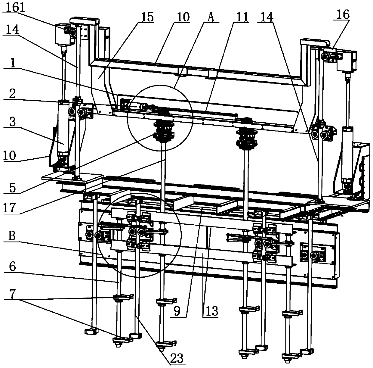
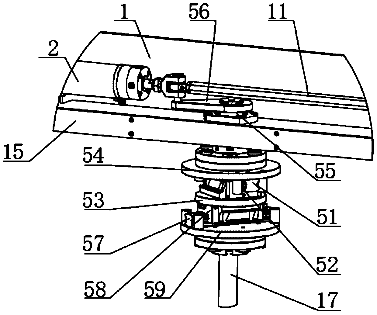
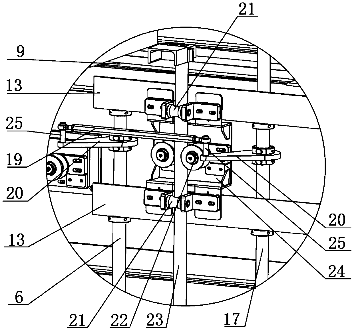
[0029] like figure 1 As shown, the hot blast stove lifting device of the present embodiment includes a support 15, and the support 15 forms a U-shaped structure. On both sides of the U-shaped structure, a side plate 1 is installed on the upper surface of the middle part, and a cylinder 2 is installed along the surface of the side plate 1. A connecting rod 11 is connected to the piston rod, and two couplings are installed at intervals on the connecting rod 11. 5. Each coupling 5 is connected to a driving shaft 17, and each driving shaft 17 is connected to a driven shaft 6 through a transmission mechanism. The driving shaft 17 and the driven shaft 6 are installed with claws at intervals along the axial direction. Disk 7, driving shaft 17 and driven shaft 6 are arranged in parallel.

[0030] like figure 2 As shown, the installation struct...


PUM


Abstract

The invention relates to a hot-blast stove lifting device which comprises a support. The support is of a U-shaped structure; two ends of the U-shaped structure are connected with piston rods of air cylinders I through connecting plates; the air cylinders I are located on two sides of the lower part of the support; a side plate is arranged on the upper surface of the middle part of the U-shaped structure; an air cylinder II is arranged along the surface of the side plate; a connecting rod is connected onto a piston rod; two couplers are arranged on the connecting rod at an interval; a driving shaft is connected onto each coupler; a driven shaft is connected onto each driving shaft through a transmission mechanism; installation claw plates are arranged on the driving shaft and the driven shaft along the axial direction at intervals; and the driving shaft and the driven shaft are arranged in parallel. The hot-blast stove lifting device provided by the invention is novel in structure, reasonable in design and reliable in power, the functions of radial rotating and axial lifting are realized, and the space utilization ration in a stove and the production efficiency are greatly improved.

Description

technical field [0001] The invention relates to the technical field of hot blast stoves, in particular to a lifting device for hot blast stoves. Background technique [0002] Existing hot blast stove devices, such as carpet heating furnaces, are usually equipped with a fixed bearing mechanism to carry the carpet so that it can be heated in contact with hot air at a fixed position. It takes a long time to heat the carpet once, and the efficiency is low, and The thermal efficiency of the heating furnace is low, and the utilization rate of the internal space is low; and the heating furnace with a multi-layer carrying mechanism is not convenient to install a lifting mechanism due to its limited internal space, so that the multi-layer carrying mechanism can only accept the loading frame at a fixed position , it is impossible to make the loading frame on different heights flow in the vertical direction, so as to realize the purpose of prolonging the heating time in the furnace. ...

Claims


Application Information

Patent Timeline
IPC IPC(8): F24H9/06
CPCF24H9/06
Inventor 施洪明
Owner 无锡研中科技有限公司
Learn More