Floor plane graph generation method and device
A type of house drawing and house type technology, applied in special data processing applications, instruments, electrical digital data processing, etc., can solve the problems of complex content of construction drawings, easy drawing omissions, and long time-consuming, so as to improve drawing efficiency and accuracy Effect
- Summary
- Abstract
- Description
- Claims
- Application Information
AI Technical Summary
Problems solved by technology
Method used
Image

Examples
Embodiment 1
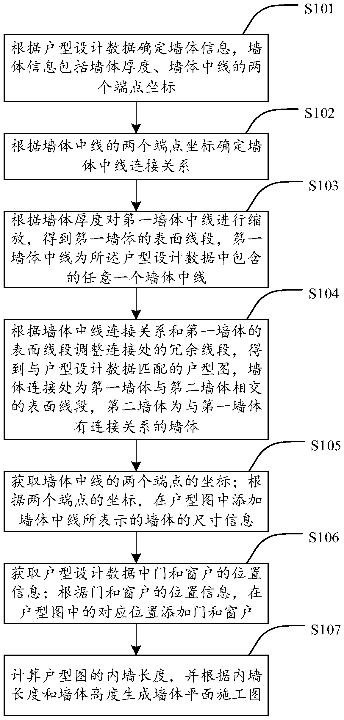
[0038] The embodiment of the present invention provides a method for generating a floor plan, such as figure 1 As shown, the method includes the following steps:
[0039] S101: Determine wall information according to the house type design data, where the wall information includes wall thickness and two endpoint coordinates of the wall centerline.
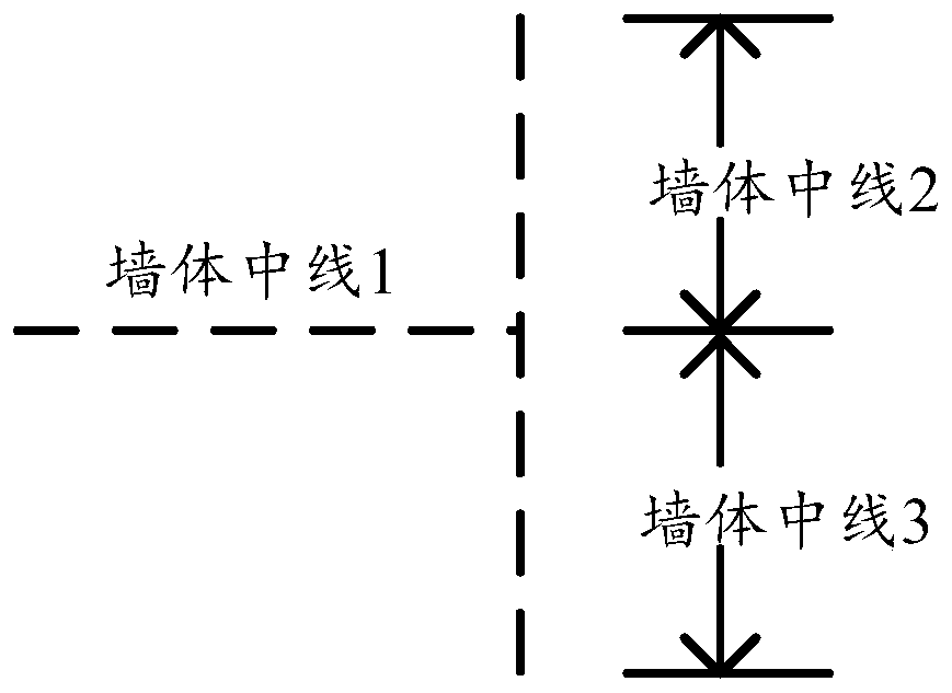
[0040] House type design data includes room numbers, wall numbers, wall information, door and window position information, and furniture layout information corresponding to each room. Each wall has a number, and each numbered wall is a continuous wall with no angle change, such as Figure 2a As shown, the wall midline 1 is the midline of the wall 1, and the wall 1 is connected to the right wall, and the right wall is divided into a wall 2 and a wall 3. The position information of the door and the window includes the size information of the door and the window itself, the wall number corresponding to the door and the window, and th...
Embodiment 2
[0115] An embodiment of the present invention provides a device for generating a floor plan, such as Figure 12 As shown, the device includes:
[0116] The screening module 21 is configured to determine wall information according to the house type design data, and the wall information includes the thickness of the wall and the coordinates of two endpoints of the centerline of the wall. House type design data includes room numbers, wall numbers, wall information, door and window position information, and furniture layout information corresponding to each room. When it is necessary to derive the planar floor plan (for example, CAD drawing) used for construction from the floor plan data, the wall information is screened out from the floor plan data, and the wall information includes the wall thickness and the two endpoint coordinates of the wall centerline. The wall centerline is the line segment in the middle of the wall parallel to the outer and inner surfaces of the wall.
...
Embodiment 3
[0133] An electronic device provided by an embodiment of the present invention, such as Figure 13 As shown, the electronic device includes a processor 41 and a memory 42, the memory stores a computer program that can run on the processor, and when the processor executes the computer program, the method provided by the first embodiment above is implemented. step.
[0134] see Figure 13 , the electronic device further includes: a bus 44 and a communication interface 43 , the processor 41 , the communication interface 43 and the memory 42 are connected through the bus 44 . The processor 41 is used to execute executable modules, such as computer programs, stored in the memory 42 .
[0135] Wherein, the memory 42 may include a high-speed random access memory (RAM, Random Access Memory), and may also include a non-volatile memory (non-volatile memory), such as at least one disk memory. The communication connection between the system network element and at least one other networ...
PUM
 Abstract
Description
Claims
Application Information
 - R&D
- Intellectual Property
- Life Sciences
- Materials
- Tech Scout
- Unparalleled Data Quality
- Higher Quality Content
- 60% Fewer Hallucinations
Browse by: Latest US Patents, China's latest patents, Technical Efficacy Thesaurus, Application Domain, Technology Topic, Popular Technical Reports.
© 2025 PatSnap. All rights reserved.Legal|Privacy policy|Modern Slavery Act Transparency Statement|Sitemap|About US| Contact US: help@patsnap.com