Hybrid synchronous reluctance motor with axially interleaved self-cooled rotor

A synchronous reluctance motor, interleaved technology, applied in synchronous machine parts, magnetic circuit rotating parts, magnetic circuit shape/style/structure, etc. The problems of high temperature of rotor core and ferrite permanent magnet poles and low utilization rate of cooling gas in the motor can increase the surface heat dissipation coefficient, enhance the ability to start under heavy load, and reduce the temperature.

Active Publication Date: 2021-02-12
HARBIN UNIV OF SCI & TECH
View PDF5 Cites 0 Cited by
  • Summary
  • Abstract
  • Description
  • Claims
  • Application Information

AI Technical Summary

Problems solved by technology

[0005] The purpose of the present invention is to provide a hybrid synchronous reluctance motor with an axially staggered self-cooling rotor to solve the problem of high temperature of the rotor iron core and ferrite permanent magnet poles of the traditional permanent magnet assisted synchronous reluctance motor and the problem of cooling gas in the motor The problem of low utilization rate and the inability to rely on the structural characteristics of the rotor to achieve self-starting improves the utilization rate of the cooling fluid in the motor, effectively reducing the temperature of the rotor core and ferrite permanent magnet poles, and can also rely on the rotor's own structure Features Realize heavy-duty start, lower manufacturing cost and more significant energy saving

Method used


Image

  • Hybrid synchronous reluctance motor with axially interleaved self-cooled rotor
  • Hybrid synchronous reluctance motor with axially interleaved self-cooled rotor
  • Hybrid synchronous reluctance motor with axially interleaved self-cooled rotor

Examples


specific Embodiment approach 1

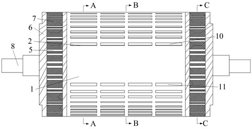
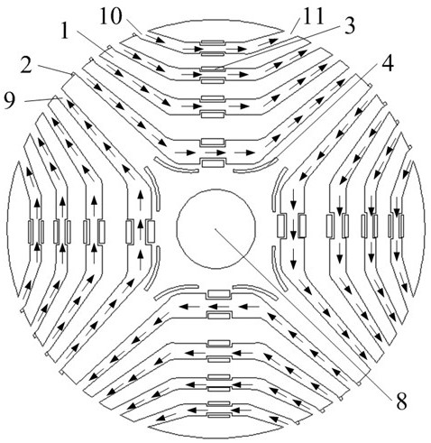
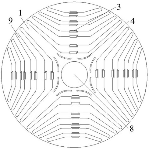
[0030] Specific implementation mode one: combine figure 1 , figure 2 , image 3 , Figure 4 and Figure 5 Describe this embodiment. The hybrid synchronous reluctance motor with an axially staggered self-cooling rotor described in this embodiment includes a rotor laminated core 1, a rotor wind-inducing plate 2, a ferrite permanent magnet pole 3, and a "bow-shaped "Magnetic attraction hole 4, "double convex" copper-nickel alloy starting cage bar 5, rotor end ring 6, rotor integral core 7, rotor shaft 8 and rotor magnetic barrier 9.

[0031] "Double convex" copper-nickel alloy starting cage bar 5 is composed of double slender copper-nickel alloy starting cage bar 5-1 and rectangular copper-nickel alloy starting cage bar 5-2, and the rotor end ring 6 is composed of the rotor left end ring 6- 1. Rotor left-biased middle end ring 6-2, rotor right-biased middle end ring 6-3 and rotor right end ring 6-4; rotor integral core 7 consists of rotor left integral iron core 7-1 and roto...

specific Embodiment approach 2

[0039] Specific implementation mode two: combination Image 6 Describe this embodiment, the difference between this embodiment and Embodiment 1 is that the air inlet 10 of the rotor magnetic barrier 9 is opened as one along the axial direction at its corresponding circumferential position, and the air outlet of the rotor magnetic barrier 9 11 is provided as one in the axial direction at its corresponding circumferential position, which can increase the flow rate of cooling gas entering the rotor magnetic barrier 9, and further reduce the gap between the rotor laminated core 1 and the ferrite permanent magnet pole 3. temperature.

[0040] Other components and connections are the same as those in Embodiment 1.

specific Embodiment approach 3

[0041] Specific implementation mode three: combination Figure 7 Describe this embodiment. The difference between this embodiment and Embodiment 1 is that a magnetic attraction groove 12 is provided on the outer diameter of the rotor laminated core 1, which further enhances the overload capacity of the motor and improves the power density and operating efficiency of the motor. .

[0042] Other components and connections are the same as those in Embodiment 1.


PUM


Abstract

The invention discloses a hybrid synchronous reluctance motor with an axial interlaced self-cooling rotor, which relates to the field of motors. The invention solves the problems that the existing permanent magnet assisted synchronous reluctance motor cannot rely on the structural characteristics of the rotor to realize self-starting, the manufacturing cost is high, and the temperature inside the rotor is high. There is a rotor magnetic barrier in the rotor laminated core, and the ferrite permanent magnet poles are installed inside the rotor laminated core. The outer diameter of the iron core is close to the air inlet of the rotor magnetic barrier, the air inlet and outlet of the rotor magnetic barrier are arranged at intervals in the circumferential direction, and the "double convex" copper-nickel alloy starting cage connected to the rotor end ring is installed on the rotor In the whole iron core, the rotor left end ring, the rotor left integral iron core, the rotor left middle end ring, the rotor lamination core, the rotor right middle end ring, the rotor right whole iron core and the rotor right end ring are press-fitted on the rotor shaft in sequence .

Description

technical field [0001] The invention relates to a hybrid synchronous reluctance motor with an axially staggered self-cooling rotor, belonging to the field of motors. Background technique [0002] In order to improve the power factor of the synchronous reluctance motor, a small amount of ferrite permanent magnet poles are inserted into the magnetic barrier of the synchronous reluctance motor rotor. The use of body permanent magnet poles is small, the price of ferrite permanent magnet poles is low, low noise, ultra-high efficiency, and no motor bearing damage caused by rotor shaft current, and it also has the high efficiency of permanent magnet motors and synchronous magnetic The low-speed and high-torque characteristics of the resistance motor. [0003] However, this kind of motor cannot achieve self-starting only relying on the structural characteristics of the rotor itself, and the temperature of the ferrite inside the rotor is relatively high during stable operation, maki...

Claims


Application Information

Patent Timeline
Patent Type & Authority Patents(China)
IPC IPC(8): H02K21/02H02K1/32
CPCH02K1/32H02K21/02
Inventor 韩继超刘玉飞董桀辰张旭戈宝军
Owner HARBIN UNIV OF SCI & TECH
Why Eureka
Try Eureka