Ring traveler

A traveler and coating technology, which is applied in coatings, textiles, papermaking, lubricating compositions, etc., to achieve the effects of improving anti-friction characteristics, improving performance, and improving wear characteristics

Pending Publication Date: 2019-07-16
BRACKER AG
View PDF7 Cites 0 Cited by
  • Summary
  • Abstract
  • Description
  • Claims
  • Application Information

AI Technical Summary

Problems solved by technology

A disadvantage of this embodiment of the hard chrome plating of the ring is that although it produces a hard, low-wear surface, the running characteristics of the traveler depend on the fiber lubricant film on the ring and on the surface of the traveler

Method used


Image

  • Ring traveler
  • Ring traveler
  • Ring traveler

Examples


Embodiment Construction

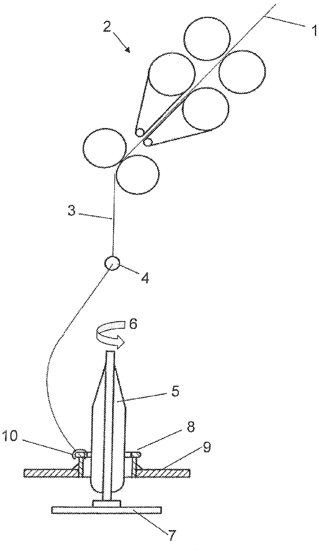
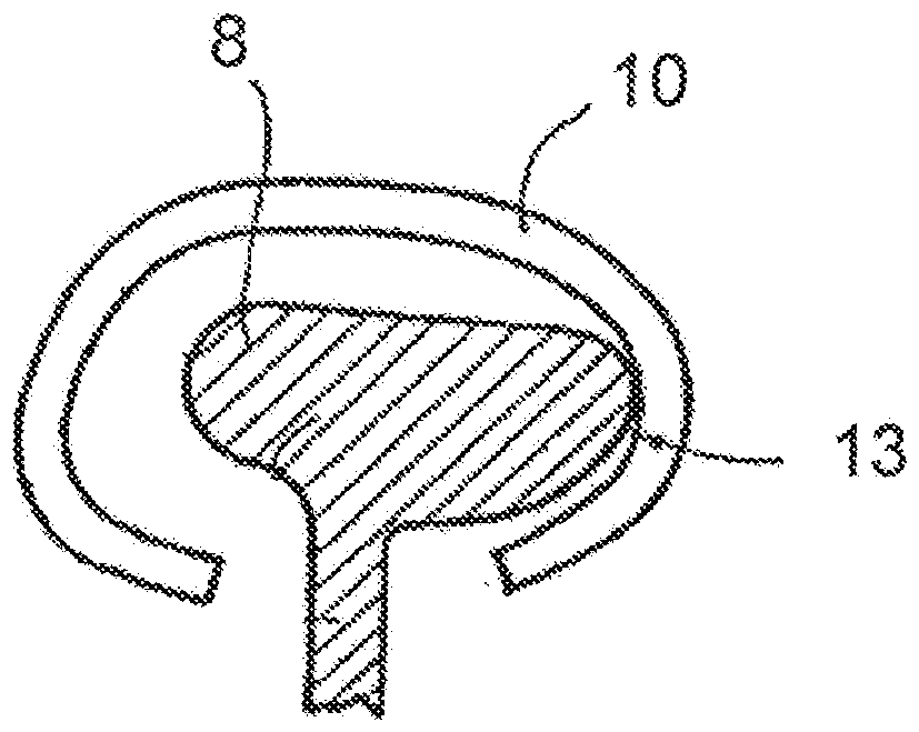
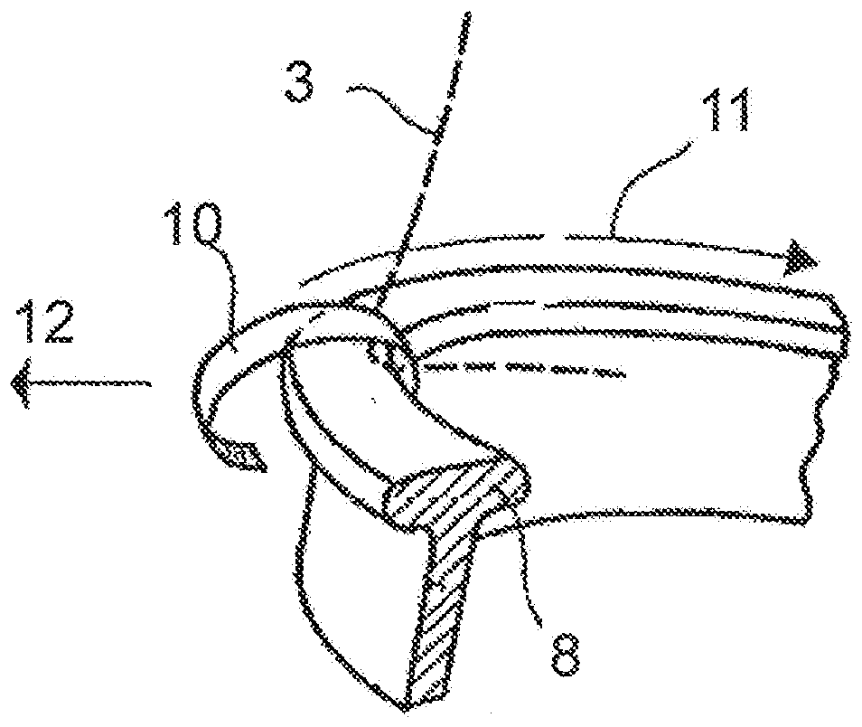
[0018] figure 1 A schematic diagram of the spinning positions of a ring spinning machine is shown, so that current ring spinning machines have up to 2000 such spinning positions. The fiber bundle (the so-called sliver 1) is fed to the take-off unit 2 in the ring spinning machine. The sliver 1 is drawn by a drawing unit 2 to form a thread 3 . The pulling unit 2 shown here is a so-called belt pulling unit, which is usually used for cotton. Depending on the application, various designs for the pulling unit 2 are known from the prior art. The wire 3 is guided to the traveler 10 via the thread guide 4 downstream of the pulling unit 2 . After passing through the traveler 10 , the thread 3 is wound onto the yarn bobbin 5 . The yarn bobbin 5 is set in rotation 6 by a drive 7 . Due to this rotation 6, the traveler 10 is entrained by the wire 3, which causes twist to be imparted to the wire 3, forming a yarn. Due to the fact that the traveler 10 is held on the ring 8 , the travele...


PUM

PropertyMeasurementUnit
Layer thicknessaaaaaaaaaa

Abstract

The invention relates to a ring traveler (10) for ring spinning or ring twisting machines, having a metallic core, wherein the metallic core is coated at least in part by a bonded coating, consistingat least of a base polymer and a solid lubricant, wherein the bonded coating has a layer thickness of 0.1 [mu]m to 50 [mu]m and the base polymer is from the group consisting of polyamides, polyamides / polyimides.

Description

technical field [0001] The invention relates to a traveler for a ring spinning machine or a ring twisting machine and a ring spinning machine or twisting machine. Background technique [0002] Travelers are used in so-called ring spinning machines or ring twisting machines, where the traveler works together with a ring and / or a twisting ring on which the traveler is placed. The traveler rotates at high speed on the top side of the ring (the so-called crown), entrained by the wire held by the traveler. This results in high loads on the contact surface of the traveler with the ring. For this reason, special attention is paid to surface properties when manufacturing rings and travelers. Rings for ring spinning machines and / or ring twisting machines must not only have a precise shape, but also have surfaces optimized to fit The ring imparts the smoothest possible running with the least wear possible. The dimensional stability and surface properties of the traveler are import...

Claims


Application Information

Patent Timeline
IPC IPC(8): D01H7/60
CPCD01H7/604C09D179/08C10M169/04C10M2201/041C10M2201/05C10M2201/065C10M2201/085C10M2201/102
Inventor M.迪佩尔B.佩迪蒙特
Owner BRACKER AG
Why Eureka
Try Eureka