
Detection device and method for rotation speed of drill bit

A technology of drill bit rotation speed and detection device, which is applied in the direction of measuring device, device using electric/magnetic method, temperature measurement of moving fluid, etc. It can solve the problem of damage to the cutting edge of the drill bit, increase the cutting heat of the drill bit and reduce the cooling effect, etc. problems, to achieve the effect of smooth waterway, increase the drilling error tolerance rate, and reduce the drilling error rate

Pending Publication Date: 2019-07-19
SHANDONG MAIRUI MEDICAL DEVICES CO LTD
View PDF0 Cites 2 Cited by
  • Summary
  • Abstract
  • Description
  • Claims
  • Application Information

AI Technical Summary

Problems solved by technology

In the artificial dental implant technology, the drill bit usually needs to be rotated at high speed, and during the dental implant process, the temperature of the drilled alveolar bone should not exceed 42 degrees, otherwise the bone tissue will be destroyed, and the effect of growing the implant and the surrounding bone tissue cannot be achieved; At present, the jaw drilling for dental implants is drilled by a motor-driven drill, and the drill is held by the dentist. In traditional dental implant surgery, the doctor holds the implanter to artificially control the drilling feed. Experienced dentists can use the drill The feeling of the hand when drilling is used to determine the information such as feed speed and strength. There is a high error rate in human operation. In case of a mistake, it will not only bring a more painful treatment experience to the patient, but may also cause bone damage due to excessive drilling temperature. The tissue is irreversibly damaged, affecting the therapeutic effect;
[0003] In terms of occupied space, the current hand-held electric drilling device, the motor is behind the drill, and needs to be very close, so the motor is in the patient's mouth during treatment, so the treatment equipment already occupies a lot of space, but it still needs to be provided. Dentists leave a large observation space, so patients need to open their mouths, which is a poor experience;
[0004] In terms of cooling, the internal cooling hole of the existing internal cooling drill bit is pierced at the top of the drill bit. This kind of internal cooling hole is pierced at the top of the drill bit. When in use, it faces the bone being drilled and receives axial pressure. It is easy for the cooling hole to be blocked, which affects the normal discharge of the coolant and reduces the cooling effect. Moreover, because the cooling hole is opened on the top of the drill bit, the cutting edge of the drill bit is damaged, which reduces the cutting effect of the drill bit and increases the cutting force, thereby increasing the drill bone. The high cutting heat makes it difficult for the dentist to grasp the feeding force, resulting in slow drilling and even damage to the surrounding bone tissue, which affects the effect of dental implants;
[0005] In order to solve the above problems, it is best to use a non-manual hand-held intraoral installation and a non-motor-driven water-driven drilling device for drilling. However, the current speed and torque of dental implants are pre-set before each drilling. Because the bone density is not uniform with the drilling path, the drilling speed and torque cannot be changed according to the bone condition, and precise control cannot be achieved. Therefore, the speed of the drill bit needs a method that can detect and automatically adjust in time in automatic drilling. device and control method

Method used


Image

  • Detection device and method for rotation speed of drill bit
  • Detection device and method for rotation speed of drill bit
  • Detection device and method for rotation speed of drill bit

Examples


Embodiment 1

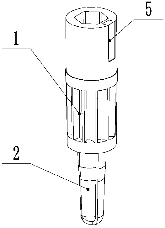
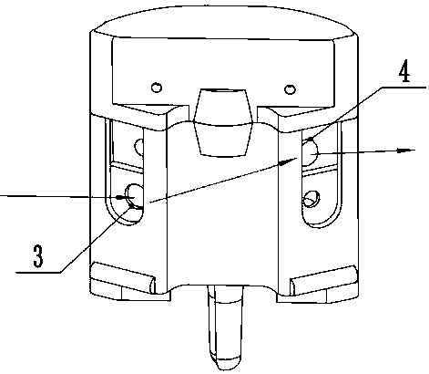
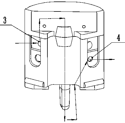
[0038]Embodiment 1, a detection device for the rotational speed of a drill, including a root bone drilling device, the root bone drilling device includes a turbine drive channel and a cleaning booster channel, and the turbine 1 drive channel includes a turbine 1, a drill bit 2 , a water inlet 3 and a water outlet 4, the cleaning booster channel includes a water inlet 3 and a water outlet 4, the drill bit 2 is fixedly connected to the turbine 1, and also includes a speed detection device and a power control device, the described The rotating speed detecting device comprises a magnet block 5 installed on the turbine 1 and a Hall sensor 6 fixed on the outside of the root bone drilling device, and the power regulating device comprises a water delivery pipe 7, a high-pressure air chamber 8, a negative pressure generator 9 and Regulating chip 10, said high-pressure air chamber 8 is filled with physiological saline, and high-pressure air chamber 8 is pressurized by an external air pum...


PUM


Abstract

The present invention discloses a detection device for a rotation speed of a drill bit and belongs to the field of biomedical devices. The detection device comprises a rotation speed detecting deviceand a power regulating device, the rotation speed detecting device comprises a magnet block arranged on a turbine and a Hall sensor fixed outside of a tooth root bone drilling device, the power regulating device comprises a water pipe and a high pressure air chamber, a negative pressure generator and a regulating chip, the high pressure air chamber is internally filled with physiological saline, the high pressure air chamber is pressurized by an external air pump, a regulating plunger is arranged on the high pressure air chamber, the regulating plunger is connected with a water inlet of the tooth root bone drilling device through the water pipe, the negative pressure generator is connected with a water outlet of the tooth root bone drilling device through the water pipe, and the water pipeis provided with a water flow monitoring device. The detection device can greatly improve accuracy and stability of drilling in dental departments, and can realize detection and regulation of the rotation speed of the drill bit.

Description

technical field [0001] The invention relates to the technical field of biomedical devices, in particular to a detection device and method for the rotational speed of a drill bit. Background technique [0002] Dental implant technology has been widely used in oral treatment. In the artificial dental implant technology, the drill bit usually needs to be rotated at high speed, and during the dental implant process, the temperature of the drilled alveolar bone should not exceed 42 degrees, otherwise the bone tissue will be destroyed, and the effect of growing the implant and the surrounding bone tissue cannot be achieved; At present, the jaw drilling for dental implants is drilled by a motor-driven drill, and the drill is held by the dentist. In traditional dental implant surgery, the doctor holds the implanter to artificially control the drilling feed. Experienced dentists can use the drill The feeling of the hand when drilling is used to determine the information such as feed...

Claims


Application Information

Patent Timeline
IPC IPC(8): A61C3/02A61C8/00G01P3/44G01K13/02
CPCA61C3/02A61C8/0089G01P3/44G01K13/02G01K13/026
Inventor 安敬滨邵润泽徐大福李娟娟
Owner SHANDONG MAIRUI MEDICAL DEVICES CO LTD
Learn More