Eureka AIR delivers breakthrough ideas for toughest innovation challenges, trusted by R&D personnel around the world.

Haze reducing and white smoke eliminating tower for flue gas

A flue gas and whitening technology, applied in the separation of dispersed particles, chemical instruments and methods, combined devices, etc., can solve the problems of visual pollution, increase cost, complicated process layout, etc., and achieve the effect of reducing cost and compact structure.

Inactive Publication Date: 2019-07-19
SHANDONG NORMAL UNIV
View PDF0 Cites 0 Cited by
  • Summary
  • Abstract
  • Description
  • Claims
  • Application Information

AI Technical Summary

Problems solved by technology

In addition, wet desulfurization consumes a large amount of water during the desulfurization process, and will also form serious fog at the end of the flue gas discharge, which is the so-called "white smoke", causing visual pollution
In order to solve this problem, a GGH heater or MGGH heater is installed in the prior art process to heat and discharge the flue gas at the end. Although this measure can improve the visual effect, the installation of GGH and other equipment increases the cost. complicate process layout

Method used


Image

  • Haze reducing and white smoke eliminating tower for flue gas
  • Haze reducing and white smoke eliminating tower for flue gas
  • Haze reducing and white smoke eliminating tower for flue gas

Examples


Embodiment 1

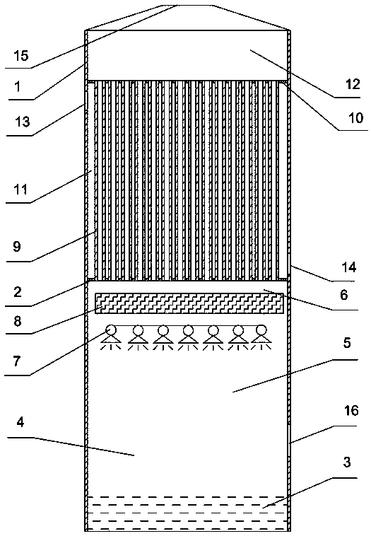
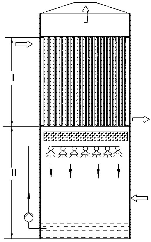
[0022] combine figure 1 and figure 2 , the present invention is described as follows:

[0023] 1. A flue gas haze reduction and "white elimination" tower, including a tower shell 1 and internal components, the cross-sectional shape of the tower body is square, and the inner chamber of the tower shell 1 is the water storage area 2 and the desulfurization flue gas from bottom to top Air intake area 3, washing area 4, defogging area 5 and heat exchange area 6, each area is connected in space, the tower shell 1 has a water supply port and a water outlet in the water storage area 2; a desulfurization flue gas intake area 3 is provided Gas inlet; scrubber 8 is arranged in the scrubbing area 4, and the scrubber 8 is connected to the washing water inlet pipe outside the tower shell 1; the scrubbing area 4 is an area for purifying and washing the desulfurized flue gas, and the washing method is water washing The desulfurization agent and desulfurization products entrained in the flu...

Embodiment 2

[0028] combine figure 1 , figure 2 , image 3 and Figure 4 , the present invention is described as follows:

[0029] On the basis of Embodiment 1, the heat exchange nozzle is provided with a cyclone plate. The cyclone plate is composed of an outer ring, an inner ring and a plurality of cyclone sheets. The cyclone sheet is rectangular and is evenly fixed between the outer ring and the inner ring. , and simultaneously deviates from the axis of the cyclone plate by an angle β. The purpose of installing the cyclone plate is that the original flue gas enters the inner cavity of the heat exchange tube through the cyclone plate. Due to the effect of the cyclone plate, the flue gas flows forward while rotating in the inner cavity of the heat exchange tube. thermal effect; secondly, it avoids the accumulation of dust in the inner cavity of the heat exchange tube, and reduces the probability of corrosion in the inner cavity of the heat exchange tube.


PUM


Abstract

The invention discloses a haze reducing and white smoke eliminating tower for flue gas. The haze reducing and white smoke eliminating tower comprises tower shell and an internal assembly, wherein a water storage zone, a desulfurization flue gas inlet zone, a washing zone, a defogging zone and a heat exchange zone are sequentially arranged from bottom to top in the inner cavity of the tower shell,and are communicated, a washing device is arranged in the washing zone, a defogging device is arranged in the defogging zone, and a heat exchange pipe bundle is arranged in the heat exchange zone. According to the present invention, raw flue gas is heated, washed and purified by the heat exchange pipe bundle to obtain desulfurized flue gas, and finally the desulfurized flue gas is subjected to haze removing and white smoke eliminating so as to achieve clean emission.

Description

technical field [0001] The invention relates to the technical field of flue gas purification equipment, in particular to a flue gas haze reduction and "white elimination" tower. Background technique [0002] The existing flue gas desulfurization methods mainly include wet desulfurization and dry desulfurization. Among them, the limestone gypsum method is the main method for wet desulfurization. This method is mature and has been adopted by most of the current flue gas desulfurization processes. use. Although the desulfurization efficiency of this method is relatively ideal, a relatively negative phenomenon will be brought about when this method is used for desulfurization, that is, a large amount of desulfurization agent and desulfurization products will be entrained in the flue gas after desulfurization. Practice and research have shown that the aggravation of smog in the current environmental pollution is directly related to the use of a large number of wet desulfurizatio...

Claims


Application Information

Patent Timeline
Patent Type & Authority Applications(China)
IPC IPC(8): B01D50/00
CPCB01D50/00
Inventor 刘明刘森
Owner SHANDONG NORMAL UNIV
Why Eureka
Eureka Blog
Learn More