Automatic feeding and drilling equipment for hardware machining

A technology of automatic feeding and drilling equipment, applied in metal processing equipment, drilling/drilling equipment, metal processing, etc., can solve problems such as threats to worker safety, high labor intensity, easy eye fatigue, etc., to ensure the qualified rate , the effect of saving energy and saving labor costs

Pending Publication Date: 2019-07-19
柏威塑胶五金制品(惠州)有限公司
View PDF0 Cites 1 Cited by
  • Summary
  • Abstract
  • Description
  • Claims
  • Application Information

AI Technical Summary

Problems solved by technology

[0006] The purpose of the present invention is to solve the problems of high labor intensity, easy fatigue of the eyes, and hidden dangers that threaten the safety of workers in the existing manual feeding method. The transmission mechanism and the drilling advance and retreat mechanism of the machine feeding method are designed separately, which is costly and takes up a lot of space. , the problem of large energy consumption

Method used


Image

  • Automatic feeding and drilling equipment for hardware machining
  • Automatic feeding and drilling equipment for hardware machining
  • Automatic feeding and drilling equipment for hardware machining

Examples


Embodiment Construction

[0027] The following will clearly and completely describe the technical solutions in the embodiments of the present invention with reference to the drawings in the embodiments of the present invention. Apparently, the described embodiments are only some of the embodiments of the present invention, but not all of them. Based on the embodiments of the present invention, all other embodiments obtained by persons of ordinary skill in the art without creative efforts fall within the protection scope of the present invention.

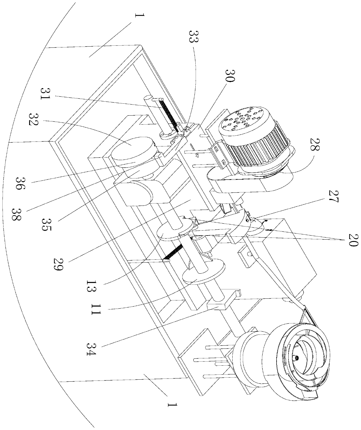
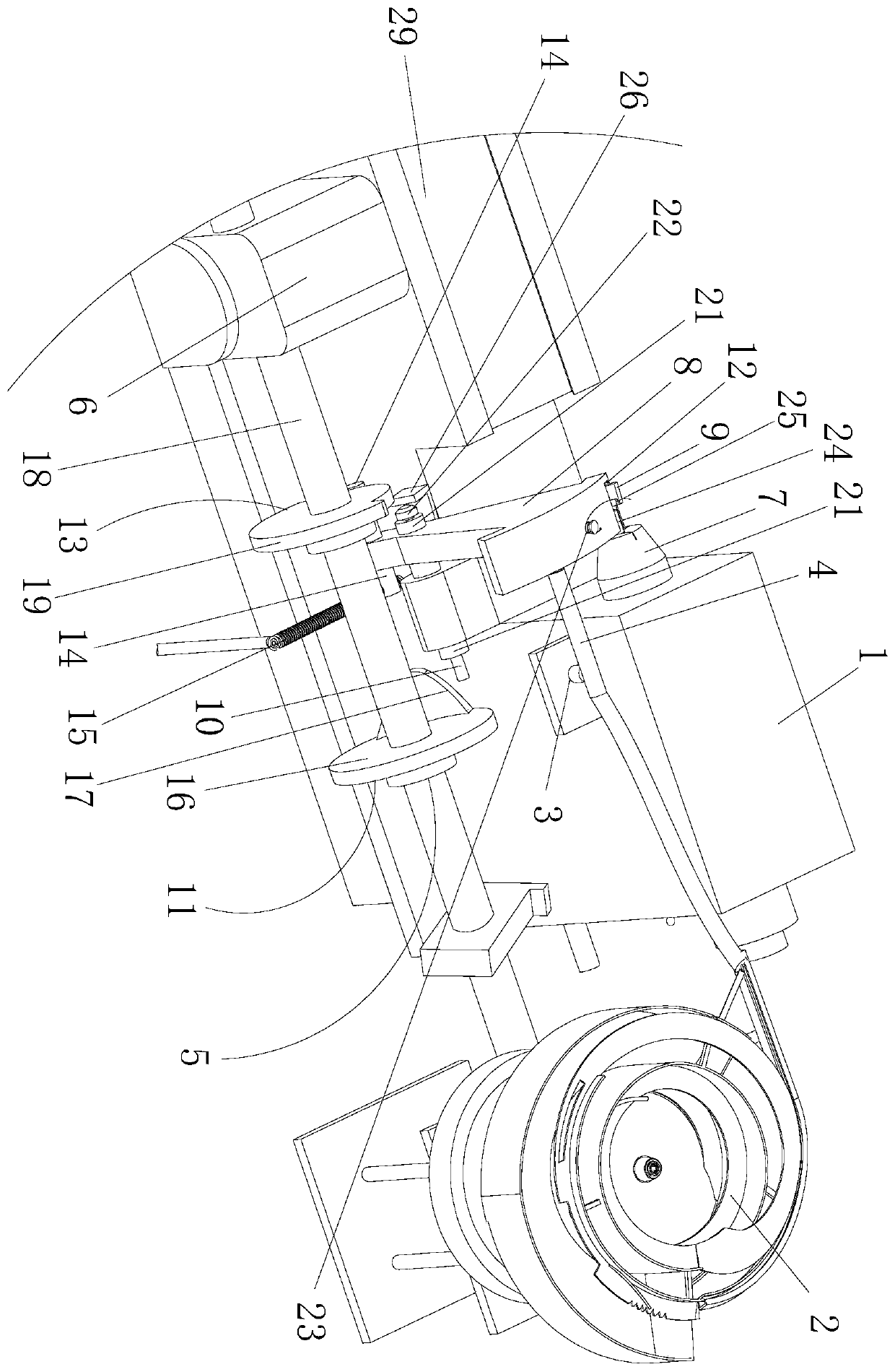
[0028] like Figure 1 to Figure 3 As shown, an automatic feeding and drilling equipment for hardware processing, including a machine tool 1, a feeding pipe assembly near one end of the machine tool 1, respectively connected to the feeding pipe assembly and the feeding mechanism at one end of the machine tool 1, installed The cam assembly 5 on one side of the machine tool 1 and the drilling machine assembly 28 located at the other end of the machine tool 1 ar...


PUM


Abstract

The invention discloses automatic feeding and drilling equipment for hardware machining. The automatic feeding and drilling equipment includes a machine tool, a feed delivery pipe assembly, a feedingmechanism, a cam assembly mounted on one side of the machine tool, a drilling machine assembly located at the other end of the machine tool and a sliding mechanism connected with the drilling machineassembly and the cam assembly. The feeding mechanism includes a material swinging part, a material plucking part and a top rod, a material receiving groove is formed in the upper part of the materialswinging part, a rotating arm is arranged on the lower part of the material swinging part, the sliding mechanism includes a base located at the other end of the machine tool and a sliding seat matchedwith the base, the middle of the outer end of the sliding seat is connected with one end of a second tension spring, the other end of the second tension spring is fixed to a support of the outer endof the base, a pushing block connected with a third cam in the cam assembly is arranged on the side, close to the cam assembly, of the outer end of the sliding seat, and the feed delivery pipe assembly includes a vibrating disc and a feed delivery pipe, wherein one end of the feed delivery pipe is connected with the vibrating disc, and the other end of the feed delivery pipe is connected with a material pipe support. According to the automatic feeding and drilling equipment, the space is saved, energy is saved, the labor cost is saved, automatic machining is achieved, the production efficiencyis improved, and the machining yield of hardware is guaranteed.

Description

technical field [0001] The invention relates to the field of hardware processing and production, in particular to an automatic feeding and drilling equipment for hardware processing. Background technique [0002] In the current domestic hardware processing and production process, the existing feeding methods and advance and retreat mechanisms have the following defects: [0003] (1) The manual feeding method is labor-intensive, easy to fatigue the eyes, and has hidden dangers that threaten the safety of workers. [0004] (2) The transmission mechanism of the machine feeding method and the drilling advance and retreat mechanism are designed separately, which has high cost, large space occupation and large energy consumption. [0005] In order to overcome the above shortcomings, we have invented an automatic feeding and drilling equipment for hardware processing. Contents of the invention [0006] The purpose of the present invention is to solve the problems of high labor ...

Claims


Application Information

Patent Timeline
Patent Type & Authority Applications(China)
IPC IPC(8): B23Q7/00B23B47/00
CPCB23B47/00B23Q7/00
Inventor 顏文成顏誌宏黃伯强丁飞曾哲兵
Owner 柏威塑胶五金制品(惠州)有限公司
Why Eureka
Try Eureka