Supporting roller inner hole machining device and machining method thereof
A processing device and processing method technology, applied in metal processing equipment, manufacturing tools, grinding workpiece supports, etc., can solve the problems of poor concentricity between the inner hole and the outer circle of the support roller, troublesome operation, and not easy enough to achieve surface quality. Good, uniform clamping force distribution, avoiding force concentration
- Summary
- Abstract
- Description
- Claims
- Application Information
AI Technical Summary
Problems solved by technology
Method used
Image
Examples
Embodiment 1
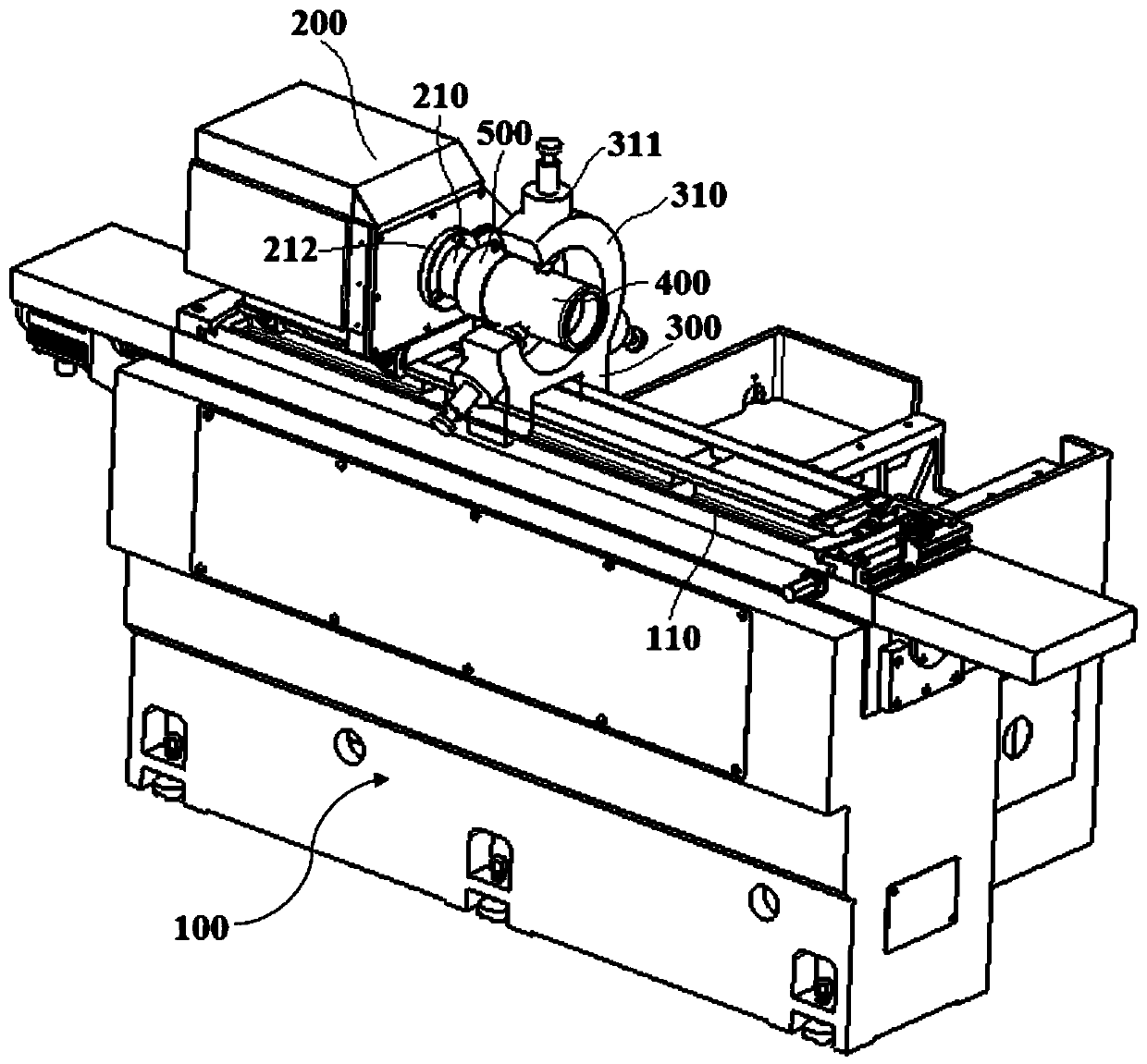
[0046] combine figure 1 , a support roller inner hole processing device in this embodiment includes a grinder body 100, a motor box 200, a center frame 300, and a grinding mechanism are arranged on the grinder body 100, and the center frame 300 and the grinding mechanism are all arranged on the grinder body 100 On the guide rail, the grinding mechanism slides along the guide rail to feed the workpiece 400 in the axial direction, and the steady frame 300 slides along the guide rail to adjust the position in time to adapt to workpieces 400 of different lengths and sizes. Specifically, the grinding mechanism in this embodiment includes a motor, a rotating shaft, and a grinding head mounted on the rotating shaft. The motor drives the rotating shaft to rotate, thereby driving the grinding head to finely grind the inner circle of the workpiece 400 .
[0047] In this embodiment, a connection plate 210 is provided on the side of the motor box 200 close to the center frame 300. The con...
Embodiment 2
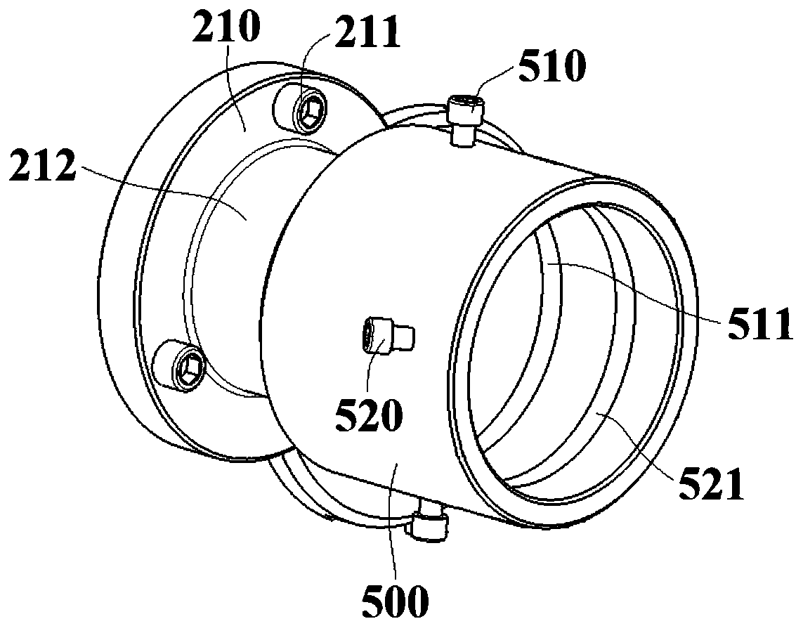
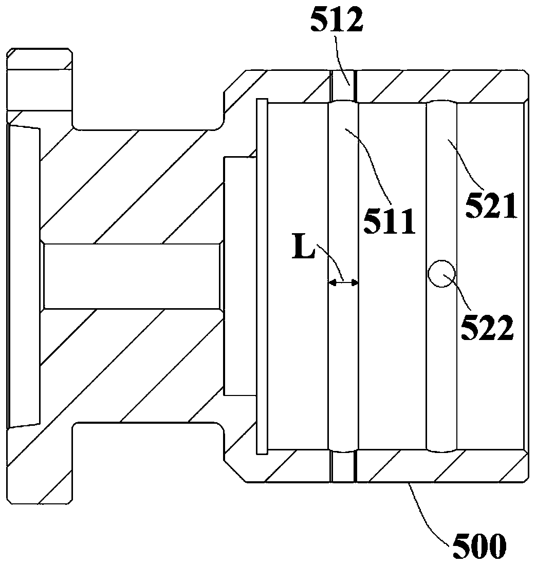
[0051] combine figure 2 and image 3 , a support roller inner hole processing device of this embodiment, its structure is basically the same as that of Embodiment 1, further: specifically, in this embodiment, two groups of grooves are provided in the flange sleeve 500, and the grooves include the first groove 511 and the second groove 521, the first groove 511 and the second groove 521 are all annular grooves opened along the circumferential direction of the flange sleeve 500, and the two groups of grooves are arranged equidistantly along the length direction of the flange sleeve 500, here The length direction is the axial direction of the flange sleeve 500 .
[0052] Further, in this embodiment, at least two sets of through holes are provided in each set of grooves, the through holes are arranged along the circumference of the flange sleeve 500, and the locking screws pass through each through hole to lock the workpiece 400, specifically, the first recess There are two set...
Embodiment 3
[0058] combine Figure 4 , a support roller inner hole processing device of this embodiment, its structure is basically the same as that of Embodiment 2, the difference is that: in this embodiment, three groups of first through holes 512 are set in the first groove 511, and the second groove Three sets of second through-holes 522 are provided in the groove 521, and the first through-holes 512 and the second through-holes 522 are arranged in a staggered manner. The holes 522 are also equidistantly arranged along the circumferential direction of the groove, and the surface where the locking screw is located is cross-sectioned to obtain a circular cross-section, specifically as Figure 4 As shown, the included angle between each locking screw and the line formed by the center of the circle is 60°.
[0059] Further, combine Figure 5 and Figure 6 , a support roller inner hole processing device of the present embodiment, the center frame 300 includes a base and two sets of supp...
PUM
 Abstract
Description
Claims
Application Information
 - R&D
- Intellectual Property
- Life Sciences
- Materials
- Tech Scout
- Unparalleled Data Quality
- Higher Quality Content
- 60% Fewer Hallucinations
Browse by: Latest US Patents, China's latest patents, Technical Efficacy Thesaurus, Application Domain, Technology Topic, Popular Technical Reports.
© 2025 PatSnap. All rights reserved.Legal|Privacy policy|Modern Slavery Act Transparency Statement|Sitemap|About US| Contact US: help@patsnap.com


