Hydraulic direct-drive three-freedom spherical wrist

A degree of freedom and spherical technology, applied in the field of robotics, can solve the problems of poor dynamic response characteristics of joints, high manufacturing/maintenance costs, low load/weight ratio, etc., to achieve easy wrist posture control, simple kinematics characteristics, load/ The effect of high self-weight ratio

Inactive Publication Date: 2019-07-19
TAIYUAN UNIV OF TECH
View PDF6 Cites 5 Cited by
  • Summary
  • Abstract
  • Description
  • Claims
  • Application Information

AI Technical Summary

Problems solved by technology

[0005] The motion transmission chain of the wrist joint is long, the mechanical structure of the wrist unit is complex, the manufacturing / maintenance cost is high, the dynamic response characteristics of the joint are poor, the load / weight ratio is low, and it cannot be used in sensitive electromagnetic environment conditions;
[0006] In terms of the two core components of motor-driven wrist reducer and servo drive system, there is a big gap between my country and developed countries such as Japan and Germany. In particular, high-precision reducers and servo drive systems are heavily dependent on imports, resulting in high cost of domestic industrial manipulators. , seriously restricting the development of my country's robot industry and the formation of international competitiveness

Method used


Image

  • Hydraulic direct-drive three-freedom spherical wrist
  • Hydraulic direct-drive three-freedom spherical wrist
  • Hydraulic direct-drive three-freedom spherical wrist

Examples


Embodiment Construction

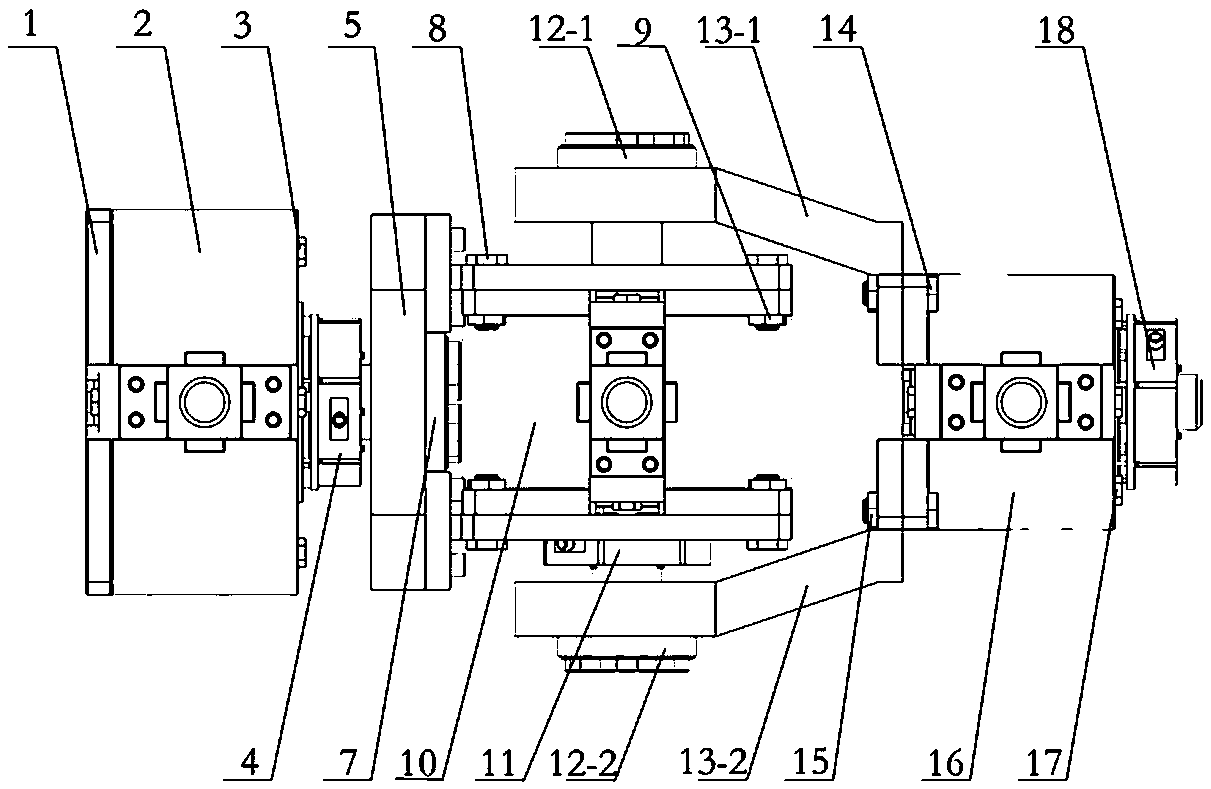
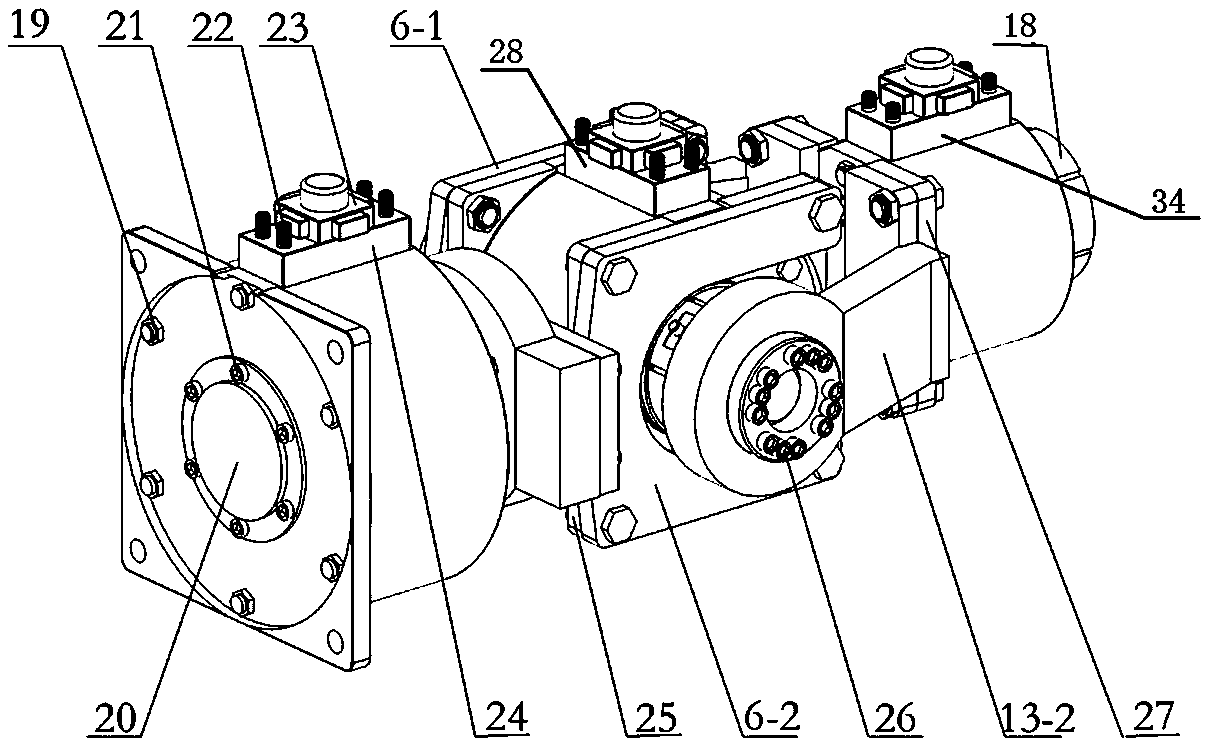
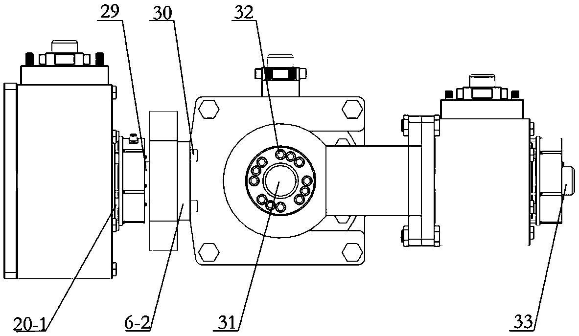
[0023] combine Figure 1-Figure 6 To describe the embodiment of the present invention in detail, the hydraulic direct-drive three-degree-of-freedom spherical wrist of this embodiment includes the first-stage hydraulic swing cylinder 2, the first-stage hydraulic swing cylinder shaft 29, and the first-stage hydraulic swing cylinder shaft 29. The first-stage angle sensor 4, the flange plate 1 of the first-stage hydraulic swing cylinder can be fixedly connected with the flange plate of the mechanical arm through bolts, and the long bolts 3 and long bolts and nuts 19 are fixedly connected to different parts of the shell of the first-stage hydraulic swing cylinder In one piece, the bearing rear end cover 20 is fixed on the motor casing by the end cover fixing screw 21 and has good sealing performance, the bearing front end cover 20-1 is fixed on the motor casing and has good sealing performance, the first stage hydraulic pressure The swing cylinder rotating shaft 29 is fixedly conne...


PUM


Abstract

The invention discloses a wrist unit which is realized based on a direct-drive joint of a hydraulic swing cylinder, and relates to an industrial robot spherical wrist. During non-singular configuration, axes of rotary shafts of hydraulic swing cylinders of three stages are mutually and perpendicularly crossed on one point in space to define a spherical wrist structure. The hydraulic swing cylinderat the first stage realizes deflection of the spherical wrist, and can realize a maximal deflection angle of 220 degrees; and the two ends of the rotary shaft of the hydraulic swing cylinder at the second stage extend out of the swing cylinder end covers to realize pitching of the spherical wrist, so that a maximal pitching angle of 220 degrees can be realized. The hydraulic swing cylinder at thethird stage realizes turnover of the spherical wrist, so that a maximal turnover angle of 225 degrees can be realized. The hydraulic direct-drive three-freedom spherical wrist disclosed by the invention does not need to use a high-precision speed reducer, has a series of advantages of being simple in structure, great in density, high in load/specific gravity ratio, strong in bearing ability, andthe like, and is suitable for working conditions such as large-power heavy-load drive and electromagnetic environmental sensitivity.

Description

technical field [0001] The invention relates to the field of robots, in particular to a hydraulic direct-drive three-degree-of-freedom spherical wrist for industrial robots. Background technique [0002] Industrial robot (manipulator) is an important supporting technology of a country's advanced manufacturing industry and an important production equipment in an information society. It is of great significance to social development and enhancing military and national defense strength. Another strategic emerging industry. [0003] The wrist unit connects the robotic arm and the end effector, and its main function is to adjust the spatial attitude of the end effector to meet the job requirements. The wrist unit has an important influence on the positioning accuracy and space attitude control performance of the end effector, and its performance has become one of the main factors restricting the application of robots, and has become an important topic in robot research. In rece...

Claims


Application Information

Patent Timeline
Patent Type & Authority Applications(China)
IPC IPC(8): B25J17/00B25J19/02
CPCB25J17/00B25J19/02
Inventor 汪成文张震阳陈帅刘华权龙
Owner TAIYUAN UNIV OF TECH
Why Eureka
Try Eureka