Robot wrist unit driven by hydraulic actuator

A hydraulic actuation and robot technology, applied in manipulators, program-controlled manipulators, manufacturing tools, etc., can solve the problems of end-effector flexibility and attitude adjustment ability limitations, spherical gears are difficult to manufacture, difficult to manufacture and assemble, etc., to achieve increased It can achieve the effects of range, high load/self-weight ratio, and easy control

Pending Publication Date: 2020-10-30
TAIYUAN UNIV OF TECH
View PDF6 Cites 0 Cited by
  • Summary
  • Abstract
  • Description
  • Claims
  • Application Information

AI Technical Summary

Problems solved by technology

[0004] The traditional three-freedom wrist, such as the Pitch-yaw-roll wrist, has a complex structure, and motion interference between internal components is prone to occur, which is difficult to manufacture and assemble, and is not practical; such as a wrist based on spherical gear transmission, the wrist is composed of a series of universal joints The spherical gear is connected in series, although the structure is compact, the appearance is neat, and it can realize three degrees of freedom movement, but the manufacturing of the spherical gear is extremely difficult, and there are principle transmission errors, so there are few practical applications; another example is based on the parallel mechanism. Wrist, which has all the disadvantages of parallel mechanisms, such as poor attitude ability, small reachable space / machine space ratio, complex control technology, etc.
[0005] The mainstream motor + gear pair transmission or belt drive three-freedom wrist, such as the patent CN102029614A proposes a space robot wrist that uses universal joints and double hemispheres to realize the three-degree-of-freedom movement of the wrist, because the motion transmission is through the motor + gear pair The transmission is realized, there is an intermediate transmission link, and the transmission chain is long, so the mechanical structure is complex and not compact, and it is severely restricted by the working environment
[0006] A new type of hydraulically driven three-freedom wrist, such as the patent CN110027010A, proposes a hydraulic direct-drive spherical wrist that uses three hydraulic swing cylinders to realize three-degree-of-freedom movement of the wrist. Although there is no intermediate transmission link, the mechanical structure is simplified and the wrist is more compact. , but the self-weight of the mechanism in the pitching and swaying motion links acts on the output shaft of the autorotation link mechanism, which causes the autorotation link to bear a large additional load and increases the energy consumption of the system and the instability of the movement; For example, the patent CN110171015A proposes a hydraulically driven spherical wrist that uses a hydraulic motor and two hydraulic cylinders to realize wrist rotation, pitch and side swing movements, which solves the influence of the self-weight of the mechanism on the output of the rotation link in the pitch and side swing movements. , which greatly reduces the energy consumption loss of the system, and also improves the stability of the wrist movement, but the rotation movement of the pitch and side swing movement links is transformed from the linear movement of the hydraulic cylinder through the positional relationship between the mechanisms , there is a nonlinear transformation relationship between linear displacement and velocity to rotation angle and angular velocity. In addition, due to the constraints of the mechanism itself, the movement space is limited, resulting in the limitation of the movement angle of pitch and side swing, which makes the flexibility and attitude of the end effector The ability to adjust is severely limited

Method used


Image

  • Robot wrist unit driven by hydraulic actuator
  • Robot wrist unit driven by hydraulic actuator
  • Robot wrist unit driven by hydraulic actuator

Examples


Embodiment Construction

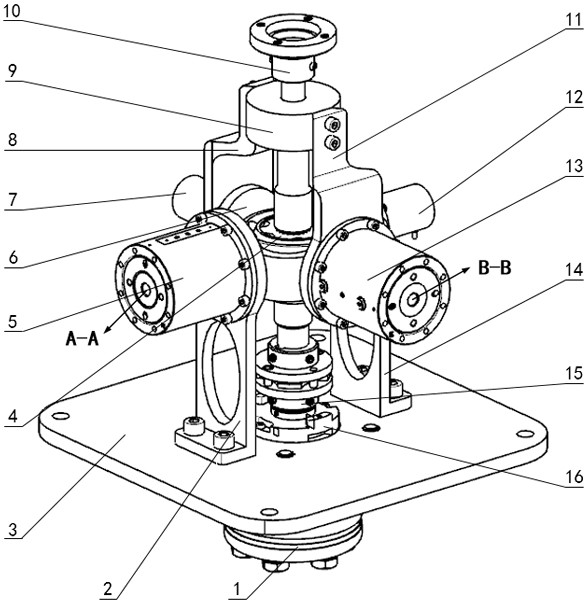
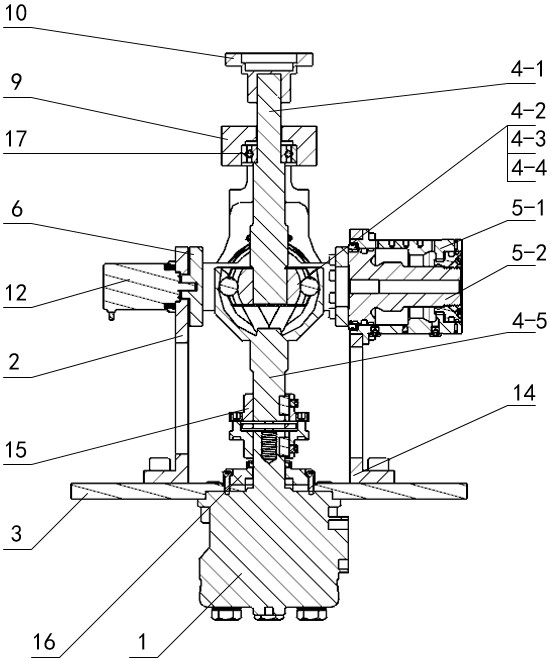
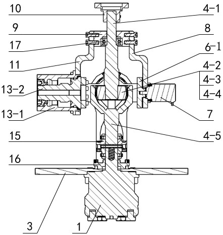
[0029] Attached below figure 1 ~ attached image 3 Embodiments of the present invention will be further described. A robot wrist unit driven by a hydraulic actuator, including a machine base 3 and a ball cage type constant velocity universal joint 4, the ball cage type constant velocity universal joint 4 includes a first transmission shaft 4-5, a second transmission shaft 4 -1, a hydraulic motor 1 is arranged at the center of the bottom of the machine base 3, the output shaft of the hydraulic motor 1 vertically penetrates the machine base 3 and is connected with the rotation angle encoder 16 and the first transmission shaft 4-5, the housing of the rotation angle encoder 16 Fixed with the machine base 3, the machine base 3 is symmetrically fixed with a vertically arranged first connecting plate 2 and a second connecting plate 14 at both ends of the rotation angle encoder 16, and the upper part of the first connecting plate 2 is fixed with a pitching hydraulic swing The cylind...


PUM


Abstract

The invention belongs to the technical field of robots, and particularity relates to a robot wrist unit capable of achieving motion decoupling and driven by a hydraulic actuator. The problems that a wrist has an intermediate transmission link due to a long transmission chain and consequently the mechanical structure is complicated and the integration level is low are solved; meanwhile, the motiondecoupling of the wrist is further achieved, and the flexibility, attitude adjusting capability and precise locating capability of an end effector are improved greatly; and the robot wrist unit comprises a hydraulic motor, hydraulic swing cylinders, angle sensors, a base, connecting ribbed plates, pitch rings, a side-sway end cover, bearings, a ball-cage type constant velocity universal joint, a coupling and an end flange connecting piece. The pitch axis, side-sway axis and rotation axis of the wrist are intersected at a point spatially to form a spherical wrist, and the decoupling of three active input motions, namely pitching, side-sway and rotation, can be achieved, so that the wrist posture control is easy and simple; and the control accuracy is high, and the phenomenon that the chattering of a mechanical arm is generated due to motion coupling during joint cooperation and adjustment is avoided effectively.

Description

technical field [0001] The invention belongs to the technical field of robot wrists, and in particular relates to a robot wrist unit driven by a motion decoupled hydraulic actuator. Background technique [0002] In today's rapidly developing society, robots are entering light industry, heavy industry, medical, military, aviation and other industries on a large scale, replacing humans to complete material transfer, assembly, classification, environmental survey, precise positioning and measurement of objects, light or micro processing And other operations, effectively reducing labor intensity, improving labor efficiency and prolonging working time, and even completing the working conditions that humans cannot handle due to various reasons. In response to this demand, many types of industrial robots have been developed. What these robots have in common is that they all need a flexible wrist mechanism to drive the end effector in order to effectively replace humans to complete ...

Claims


Application Information

Patent Timeline
Patent Type & Authority Applications(China)
IPC IPC(8): B25J9/00B25J9/14B25J17/00
CPCB25J17/00B25J9/14B25J9/0009
Inventor 汪成文陈帅吉鑫浩张震阳权龙
Owner TAIYUAN UNIV OF TECH
Why Eureka
Try Eureka