Distributing pipe inlet device for high water tank

A shunt pipe and pool technology, applied in the field of hydraulic construction, can solve the problems of suction, shunt pipe vibration, suction vortex, etc., and achieve the effects of reducing the degree of air entrainment, suppressing the formation of suction belts, and having a simple structure

Pending Publication Date: 2019-07-19
GUANGDONG RES INST OF WATER RESOURCES & HYDROPOWER
View PDF0 Cites 0 Cited by
  • Summary
  • Abstract
  • Description
  • Claims
  • Application Information

AI Technical Summary

Problems solved by technology

[0005] The technical defect of the shunt pipe in the prior art is that when the flow rate of the water supply system is small, the mouth of the conventional shunt pipe will generate a suction vortex due to insufficient submerged water depth, resulting in the vibration of the shunt pipe and a large amount of air suction.

Method used


Image

  • Distributing pipe inlet device for high water tank
  • Distributing pipe inlet device for high water tank
  • Distributing pipe inlet device for high water tank

Examples


Embodiment Construction

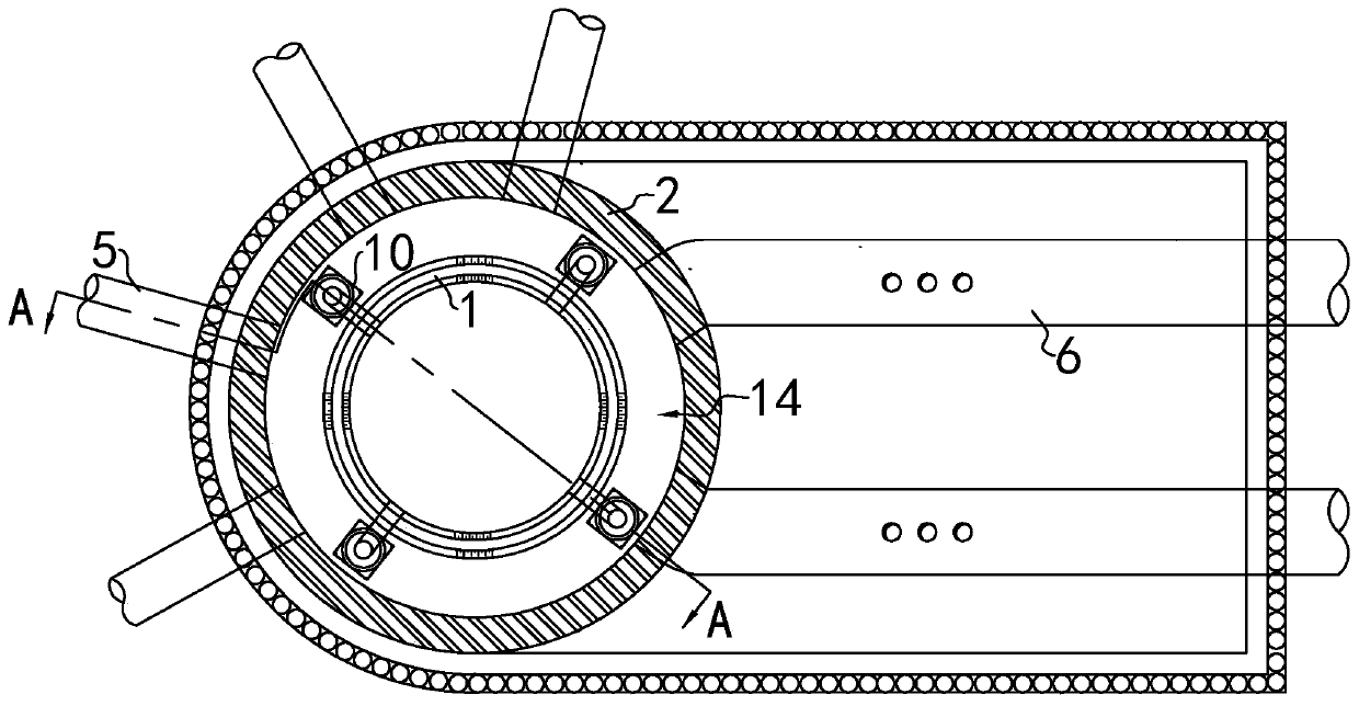
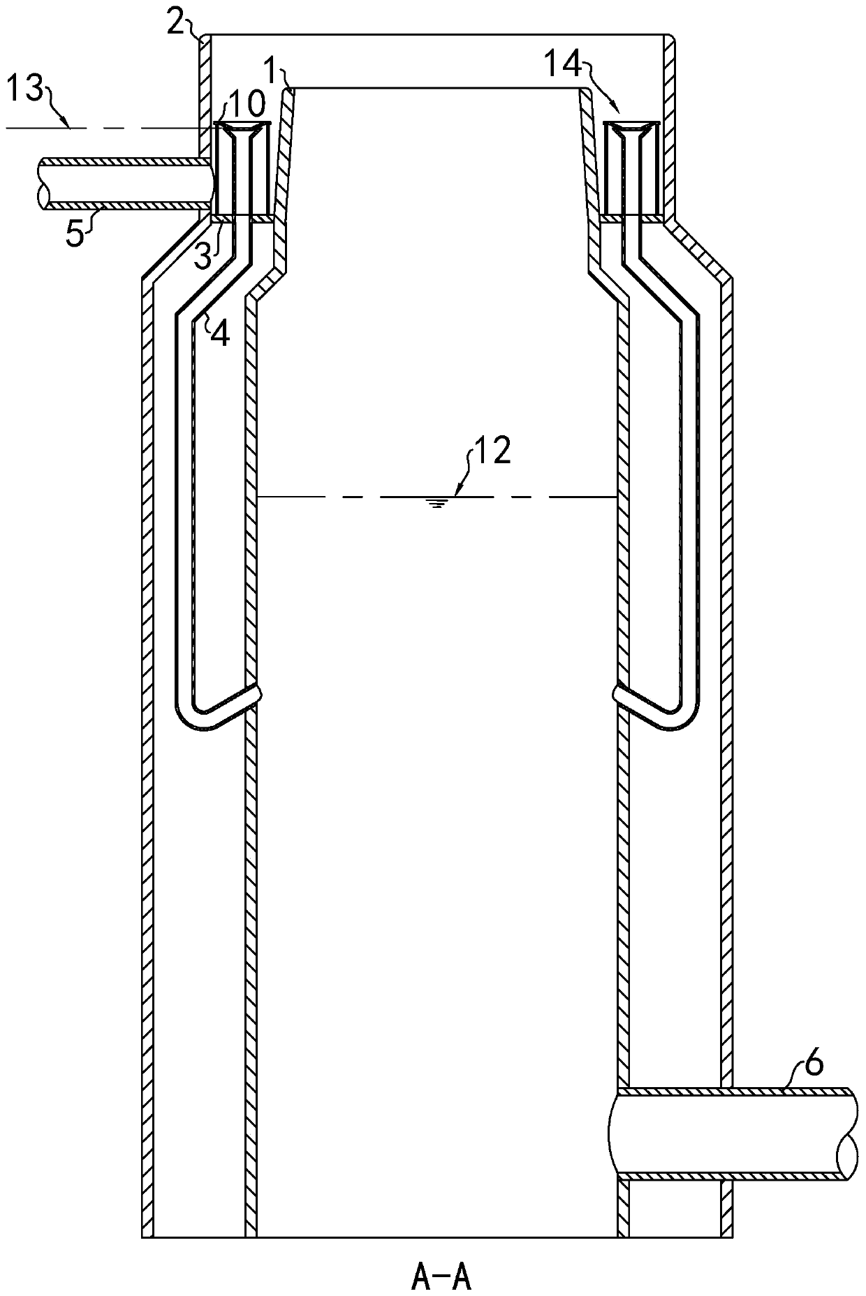
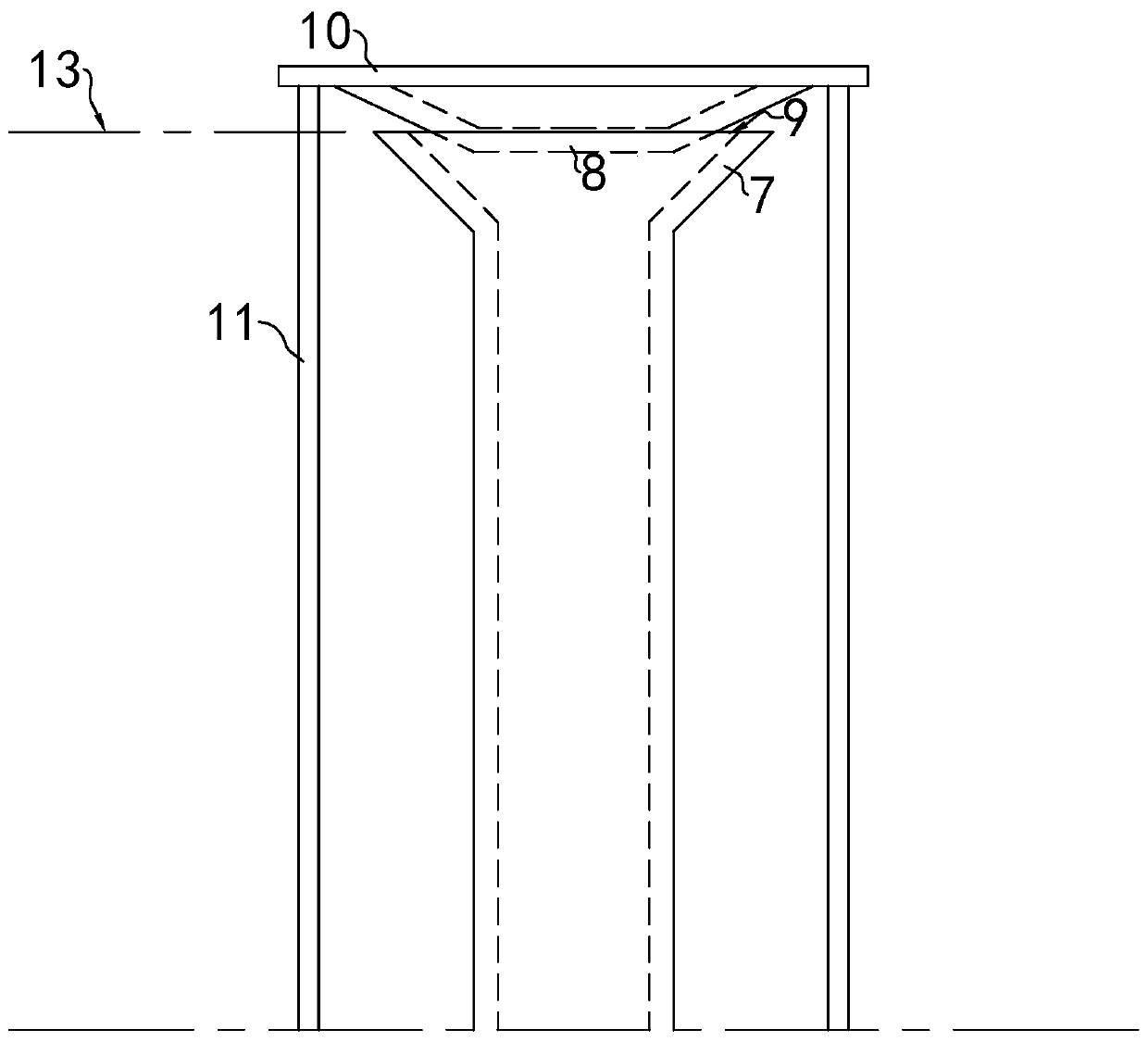
[0022] refer to Figures 1 to 5 , a shunt pipe inlet device for a high-level pool, including a pipe body and a bracket; one end of the pipe body communicates with the shunt pipe 4 of the high-level pool and the other end of the pipe body is provided with a nozzle 7, and the nozzle 7 is located in the high-level pool In the overflow tank 14; the bracket includes a raised portion 8 fixed outside the nozzle 7, the radial dimension of the nozzle 7 gradually expands from the inside of the pipe body, and the raised portion 8 protrudes into the nozzle 7, and the protrusion A flow gap 9 is provided between the portion 8 and the inner side of the nozzle 7 .

[0023] Preferably, the bracket includes a cover plate 10 , and the center of the cover plate 10 protrudes toward one side of the cover plate 10 to form a raised portion 8 .

[0024] Preferably, the bracket further includes several uprights 11, one end of the uprights 11 intersects with the cover plate 10 and the other end of the ...


PUM


Abstract

The invention discloses a distributing pipe inlet device for a high water tank, and relates to the field of hydraulic structures. The distributing pipe inlet device includes a pipe body and a support,one end of the pipe body communicates with a distributing pipe, a pipe mouth is formed in the other end of the pipe body, and the pipe mouth is arranged in an overflow groove; the support includes araised part fixed outside the pipe mouth, the radial dimension of the pipe mouth gradually expands outwards from the pipe body, the raised part protrudes into the pipe mouth, and a flow passing gap isarranged between the raised part and the inner side of the pipe mouth. The distributing pipe inlet device has the beneficial effects that the raised part is matched with the pipe mouth with the gradually expanded radial dimension to form the annular flow passing gap, the raised part is at the center of the pipe mouth, the flow passing gap can decrease the water velocity and disperse water inflow,the conditions for formation of an aspirating vortex can be destroyed, formation of a penetrating aspirating zone can be inhibited, the degree of water aeration can be decreased, water continuously and stably flows into the distributing pipe advantageously, and the distributing pipe inlet device can adapt to operational states of different water levels and flow rates. According to the technical scheme, the structure is simple, the manufacturing cost is low, and maintenance is easy.

Description

technical field [0001] The invention relates to hydraulic constructions, in particular to a shunt pipe inlet device for high-level pools. Background technique [0002] The high-level pool is a hydraulic structure specially used for long-distance water supply. Its main function is to stabilize the tail water level of the pump station and adjust the water level in the well to ensure the stability of the water supply head. The high-level pool is usually designed in a cylindrical shape. After the water enters from the water inlet pipe, it first passes through the annular overflow weir, and then overflows into the well. The lower part of the well is connected to the outlet pipe. [0003] The traditional high-level pool often has a drop of tens of meters from the annular overflow weir to the lowest operating water level. The water level drop of the traditional high-level pool is relatively large, and the drop of the water flow with such a large drop will cause a large number of a...

Claims


Application Information

Patent Timeline
Patent Type & Authority Applications(China)
IPC IPC(8): E03B11/12
CPCE03B11/12
Inventor 黄本胜刘达谭超邱静郭磊吉红香
Owner GUANGDONG RES INST OF WATER RESOURCES & HYDROPOWER
Why Eureka
Try Eureka