Multiple-stage separator

A technology of separator and cyclone separation, which is applied in the direction of production fluid, wellbore/well components, earthwork drilling and production, etc. It can solve the problems of small processing capacity, low separation efficiency and easy clogging, and achieve large processing capacity and high separation efficiency. High, the effect of preventing pipe blockage

Active Publication Date: 2019-07-19
EAST CHINA UNIV OF SCI & TECH
View PDF8 Cites 18 Cited by
  • Summary
  • Abstract
  • Description
  • Claims
  • Application Information

AI Technical Summary

Problems solved by technology

[0008] The present disclosure provides a novel multi-stage separator for in-situ sediment backfilling of natural gas h...

Method used


Image

  • Multiple-stage separator
  • Multiple-stage separator
  • Multiple-stage separator

Examples


Embodiment

[0043] 1. Process flow

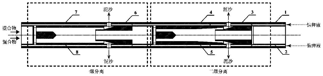
[0044] A double-layer coiled tubing drilling process was adopted in a certain natural gas hydrate fluidization production. The tool pipe string from the sea surface to the seabed consists of coiled tubing, the multi-stage separator of the present invention, nozzles, differential pressure sleeves and screw drilling tools. The fluid passes through the multi-stage separator from the annulus (that is, the annulus between the outer pipe and the inner pipe) to the nozzle, and the pressure differential sliding sleeve works during the back-up process of the drilling string, and the drilling fluid is ejected from the nozzle, and the ejected jet is due to It is a high-pressure fluid that can break the hydrate and sediment in the formation into fine particles. The drilling fluid and these fine particles are mixed into a slurry and returned from the inner tube at the bottom.

[0045] 2. Implementation effect

[0046] The returned solid-liquid two-phase flow pass...


PUM


Abstract

The invention provides a multiple-stage separator. The multiple-stage separator comprises a drilling fluid injection system, an exploitation mixture return system and a hydrocyclone separation systemplaced between the drilling fluid injection system and the exploitation mixture return system. The multiple-stage separator has the advantages that the handling capacity is large, tube plugging is notprone to occurring, and the structure is simple; and the multiple-stage separator has high application value and aims to solve the problem of sediment backfill in the process of natural gas hydrate fluidization exploitation, thus stabilization of a seabed layer is ensured, and accidents of tsunamis and the like caused by seabed cavitation due to the fact that the seabed sediment cannot be separated are avoided.

Description

technical field [0001] The disclosure relates to a downhole cyclone separator, in particular to a multistage separator used for in-situ sediment backfilling of natural gas hydrate. More specifically, the present disclosure relates to a multi-stage separator for in-situ sediment backfilling of gas hydrates and its application. Background technique [0002] Natural gas hydrate, also known as combustible ice, is a clathrate crystalline compound formed by wrapping hydrocarbon gas molecules such as methane with water molecules under low temperature and high pressure environment. Because of its wide distribution range, large reserve scale, high energy density and low environmental pollution , Gradually become an important emerging clean energy and occupy an important position in the future energy strategy. [0003] At present, natural gas hydrate exploitation mainly adopts depressurization, heat injection, agent injection, displacement and other methods, and the depressurization ...

Claims


Application Information

Patent Timeline
IPC IPC(8): E21B43/38E21B43/01
CPCE21B43/385E21B43/01E21B41/0099
Inventor 汪华林常玉龙黄渊吴霁薇李剑平朱静怡周守为付强何玉发
Owner EAST CHINA UNIV OF SCI & TECH
Why Eureka
Try Eureka