Keyboard bottom plate automatic detection device

An automatic detection device and bottom plate technology, which is applied in the detection field, can solve the problems of low accuracy and low efficiency of manual detection of the keyboard bottom plate, and achieve the effects of high accuracy, prevent accuracy, and improve detection efficiency

Active Publication Date: 2020-11-20
重庆丰川电子科技有限公司
View PDF23 Cites 0 Cited by
  • Summary
  • Abstract
  • Description
  • Claims
  • Application Information

AI Technical Summary

Problems solved by technology

[0003] The purpose of the present invention is to provide an automatic detection device for the keyboard bottom plate to solve the problems of low efficiency and low accuracy in the prior art of manual detection of the keyboard bottom plate

Method used


Image

  • Keyboard bottom plate automatic detection device
  • Keyboard bottom plate automatic detection device
  • Keyboard bottom plate automatic detection device

Examples


Embodiment 1

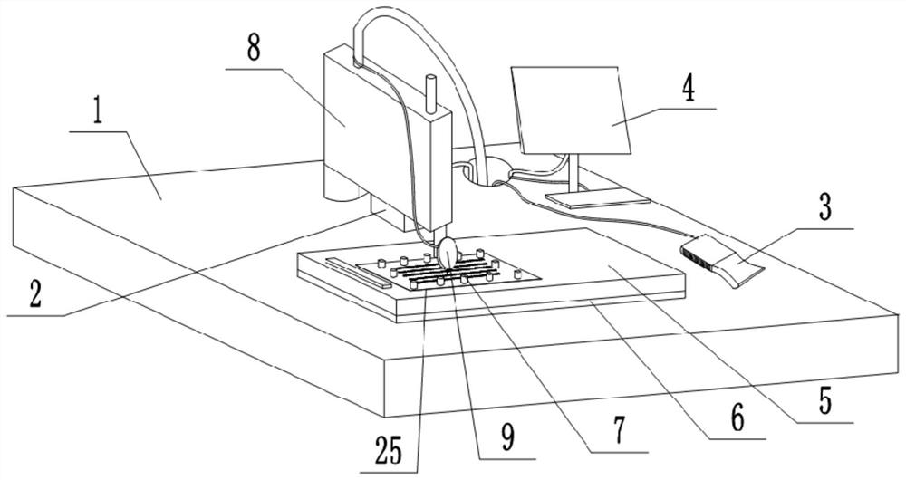
[0034] Keyboard bottom plate 25 automatic detection device, as attached figure 1 As shown, it is mainly composed of a workbench 1, a mounting base 2, a teaching pendant 3, a computer 4, a detection table 5, a manipulator 8, a digital indicator 9, an electromagnet 6, and several limit blocks 7. The mounting base 2 is installed on the rear side of the workbench 1, and the manipulator 8 is rotatably connected to the mounting base 2. The teaching pendant 3 is placed on the workbench 1 , and the teaching pendant 3 is connected with the manipulator 8 for setting programming to control the motion trajectory of the manipulator 8 . The computer 4 is installed on the rear side of the workbench 1, the digital display dial indicator 9 is installed at the bottom of the manipulator 8, the digital display dial indicator 9 is connected with the computer 4, and the read data is transmitted to the computer 4 and passed through The display of computer 4 shows, reads and calculates for operating...

Embodiment 2

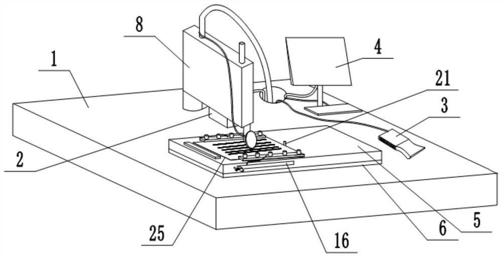
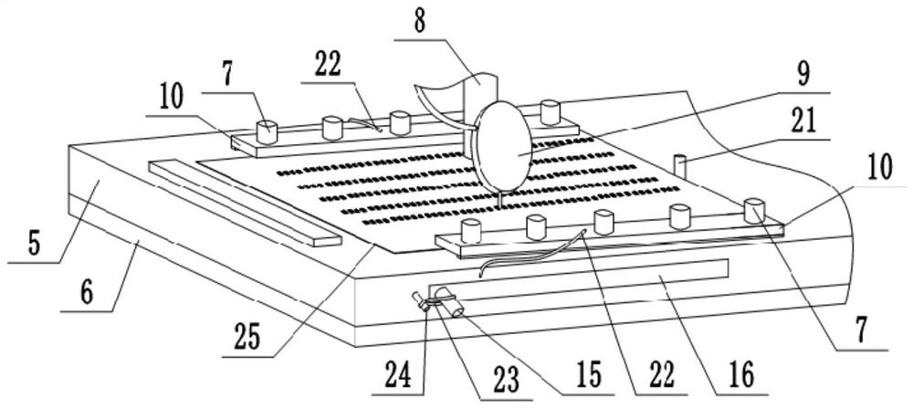
[0039] The difference between this embodiment and embodiment 1 is: as attached figure 2 , attached image 3 And attached Figure 4As shown, the front side and the rear side of the detection platform 5 are also hinged with a pressing plate 10, the pressing plate 10 is made of a material that can be attracted by the electromagnet 6, preferably iron; the bottom of the pressing plate 10 is provided with a buffer layer. Several limit blocks 7 are evenly distributed on the two pressing plates 10, and the electromagnet 6 can pass through the detection table 5 to attract the pressing plates 10 and the limiting blocks 7 when the electromagnet 6 generates magnetism; Cooperate, on the one hand can increase the contact area of ​​keyboard bottom plate 25 and pressing down part (pressing down part in the present embodiment refers to the parts that keyboard bottom plate 25 is pushed down, as pressing plate 10, limit block 7), makes the bottom of keyboard be affected. The force is more bal...


PUM


Abstract

The invention relates to the technical field of detection, and discloses an automatic keyboard bottom plate detection device. The automatic keyboard bottom plate detection device comprises a workbench; the workbench is provided with a mounting base, a demonstrator, a computer and a detection platform; a mechanical arm is rotationally connected to the mounting base, and the mechanical arm is connected with the demonstrator; a digital display dial indicator is arranged at the bottom of the mechanical arm and is connected with the computer; an electromagnet is arranged at the bottom of the detection platform, and the bottom of the electromagnet is connected with the workbench; and the top of the detection platform is detachably connected with a plurality of limiting blocks capable of being attracted by the electromagnet. According to the automatic keyboard bottom plate detection device provided by the invention, the movement track of the mechanical arm is controlled through the demonstrator; a hook on a keyboard bottom plate is detected through the digital display dial indicator, detected data are transmitted to the computer, and the data are displayed through a display of the computer, so that whether the height of the hook meets the production requirement is calculated; and the detection efficiency of the keyboard bottom plate is greatly improved, and the detection accuracy is higher than that of manual detection.

Description

technical field [0001] The invention belongs to the technical field of detection. Background technique [0002] The surface of the keyboard bottom plate has an upwardly bent hook for assembling the scissor-type connecting member. After the keyboard bottom plate is produced, it is necessary to check whether the height of the hook on the keyboard bottom plate (that is, the height from the top of the hook to the top surface of the keyboard bottom plate) meets the production requirements. The existing detection methods are all manually detected one by one, the detection efficiency is very low, and the detection results have large errors and low accuracy. Contents of the invention [0003] The object of the present invention is to provide an automatic keyboard bottom plate detection device to solve the problems of low efficiency and low accuracy in manual detection of keyboard bottom plates in the prior art. [0004] In order to achieve the above object, the basic scheme of t...

Claims


Application Information

Patent Timeline
Patent Type & Authority Patents(China)
IPC IPC(8): G01B5/06G01B5/00
CPCG01B5/0002G01B5/0018G01B5/061
Inventor 金浩
Owner 重庆丰川电子科技有限公司
Why Eureka
Try Eureka