
Torsion durability fixed torque testing machine for automobile dry friction type clutch driven plate assembly
A dry friction and clutch technology, which is used in machine gear/transmission mechanism testing, vehicle testing, and machine/structural component testing. Effectively verify the effective life of the clutch driven plate assembly and other issues, and achieve the effect of convenient operation and simple structure
- Summary
- Abstract
- Description
- Claims
- Application Information
AI Technical Summary
Problems solved by technology
Method used
Image


Examples
Embodiment
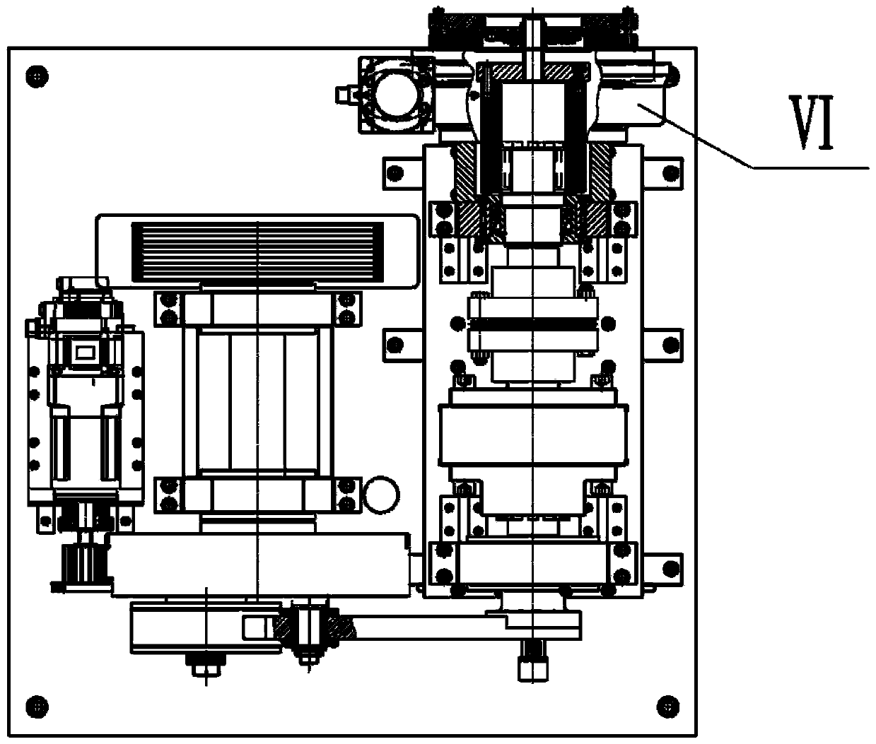
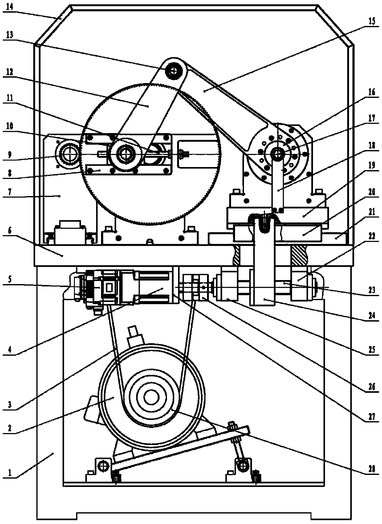
[0017] Embodiment: As shown in the accompanying drawings, this dry friction clutch driven disc assembly torsion durability constant torque testing machine for automobiles mainly includes machine base I, driving mechanism II, manual drive loading mechanism III, torsion mechanism IV, compensation Mechanism Ⅴ, centering mechanism Ⅵ, driving mechanism Ⅱ, manual drive loading mechanism Ⅲ, torsion mechanism Ⅳ and compensation mechanism Ⅴ are respectively fixed on machine base Ⅰ, centering mechanism Ⅵ is fixed on torsion mechanism Ⅳ; Frame 1, the variable frequency motor 2 is fixed on the frame 1, the small pulley 28 is installed on the output shaft of the variable frequency motor 2, and the power is transmitted to the large pulley 55 of the drive mechanism II through the V-ribbed belt 3, and the platen 6 It is fixed on the frame 1 by screws, and an outer frame 14 is fixed on the platform 6 . The compensation mechanism V is composed of a screw fixing seat A22, a screw fixing seat B25...
PUM
 Abstract
Description
Claims
Application Information