Driving shaft system rack test device and method for automobile

A bench test, drive shaft technology, applied in the direction of measuring device, vehicle test, machine gear/transmission mechanism test, etc. problems such as product quality, to achieve the effect of saving time and cost

Pending Publication Date: 2019-07-19
SOUTH CHINA UNIV OF TECH
View PDF0 Cites 3 Cited by
  • Summary
  • Abstract
  • Description
  • Claims
  • Application Information

AI Technical Summary

Problems solved by technology

[0004] At present, the main constant velocity drive shaft test benches in China can only test a few performances of the drive shaft, such as circumferential clearance, Y-direction clearance, slip curve, etc., and cannot test the Y-direction derived force and high-frequency slip resistance. , Complementary torque and other parameters that characterize NVH performance cannot guarantee the quality of constant velocity joint assembly products, and will cause repeated development of test benches and waste of human resources

Method used


Image

  • Driving shaft system rack test device and method for automobile
  • Driving shaft system rack test device and method for automobile
  • Driving shaft system rack test device and method for automobile

Examples


Embodiment Construction

[0045] In order to better understand the present invention, the embodiments of the present invention will be described in further detail below in conjunction with the accompanying drawings.

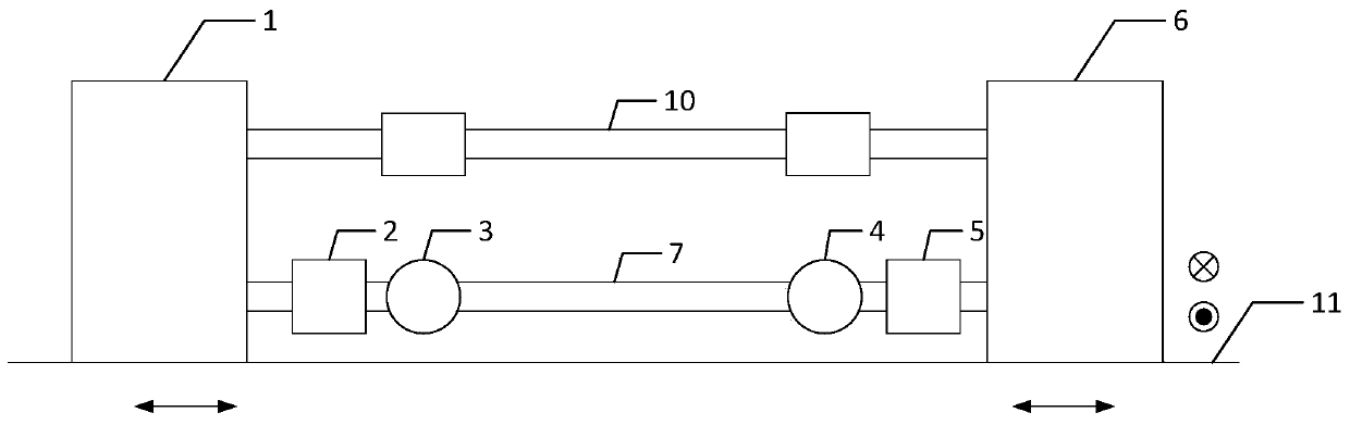
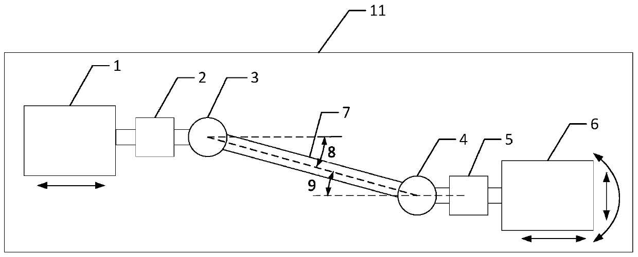
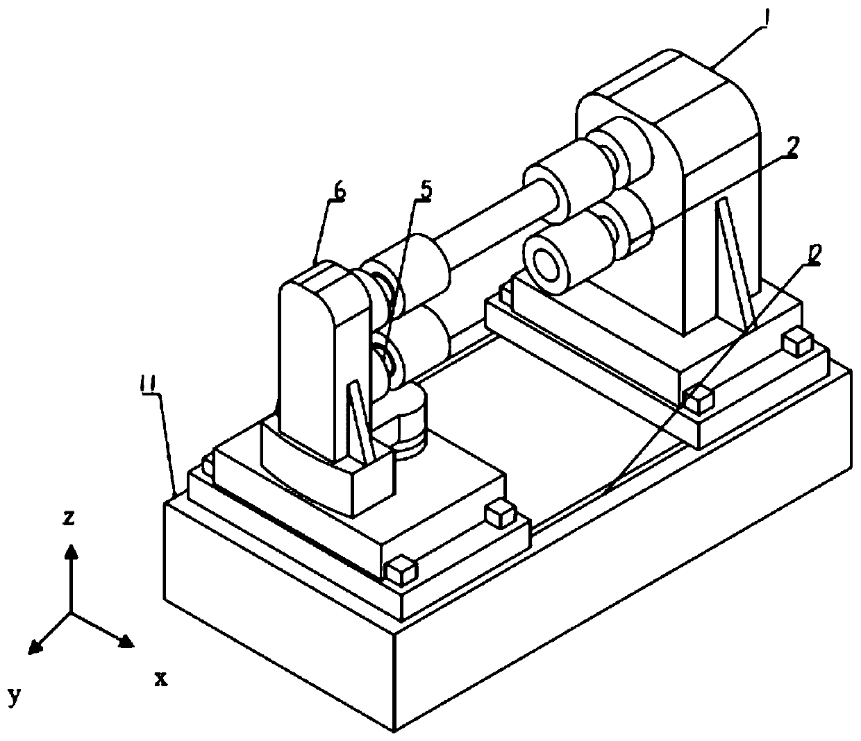
[0046] Such as Figure 1 to Figure 3 As shown, a bench test device for a drive shaft system for an automobile includes:

[0047] Base 11, the upper end surface of which is provided with two base Y-direction chute 12 in parallel along the length direction;

[0048] Relative to the drive motor mechanism 1 and the load motor mechanism 6 arranged on the upper end surface of the base 11, the drive motor mechanism 1 and the load motor mechanism 6 are both provided with upper and lower shaft clamps, wherein the upper two-axis clamp A secondary shaft 10 with universal joints at both ends is connected between them, and the two-axis clamps at the bottom of the drive motor mechanism and the load motor mechanism are respectively provided with a Y-direction force sensor 2 and a torque sensor 5; the d...


PUM


Abstract

The invention discloses a driving shaft system rack test device and method for an automobile. The driving shaft system rack test device includes a base, a temperature sensor, a control console, a driving motor mechanism and a load motor mechanism.The driving motor mechanism and the load motor mechanism are each provided with an upper shaft clamp and a lower shaft clamp, and a counter shaft is connected between the two upper shaft clamps , wherein cardan joints are arranged at the two ends of the counter shaft,a Y-direction force sensor and a torque sensor are arranged on the two lower shaft clamps of the the driving motor mechanism and the load motor mechanism correspondingly;a rotation mechanism, an X-direction prismatic pair and a Y-direction prismatic pair are sequentially arranged at the bottom of the driving motor mechanism from top to bottom; and the bottom part of the load motor mechanism is successively top-to-bottom provided with an X-direction prismatic pair and a Y-directionprismatic pair. According to the driving shaft system rack test device and method for the automobile, simulation experiments of multiple driving shaft performance parameters can be realized efficiently and accurately, experimental time and costs are saved, and effective technical support is provided for design development and performance experiments of automobile constant-speed driving shafts, especially for NVH performance verification.

Description

technical field [0001] The invention relates to a bench test device and method for an automobile drive shaft system, which are used for measuring various performance parameters of the automobile drive shaft, especially NVH performance parameters. Background technique [0002] The driving shaft of the constant velocity universal joint assembly is an important part of the automobile transmission device, which coordinates the necessary traction and speed of the automobile under various driving conditions, and ensures that the left and right driving wheels of the automobile can adapt to the differential speed requirements. The quality and reliability of its working performance directly affect the safety, stability and comfort of driving, so it must be strictly tested before use. [0003] With the widespread use of electric vehicles (the driving torque of the motor is large and can reach the maximum torque in an instant) and high-torque engines, the NVH problem of the vehicle cau...

Claims


Application Information

Patent Timeline
Patent Type & Authority Applications(China)
IPC IPC(8): G01M17/007G01M13/02
CPCG01M13/02G01M17/007
Inventor 上官文斌许承龙吕辉
Owner SOUTH CHINA UNIV OF TECH
Why Eureka
Try Eureka