Comparator circuit and comparator circuit control method
A comparator circuit, comparator technology, applied in the direction of instruments, electrical components, electrical signal transmission systems, etc., can solve the problems of high cost and large circuit area, and achieve the effect of reducing the area and saving the circuit cost.
- Summary
- Abstract
- Description
- Claims
- Application Information
AI Technical Summary
Problems solved by technology
Method used
Image

Examples
Embodiment Construction
[0026] It should be noted that, in the case of no conflict, the embodiments in the present application and the features in the embodiments can be combined with each other.
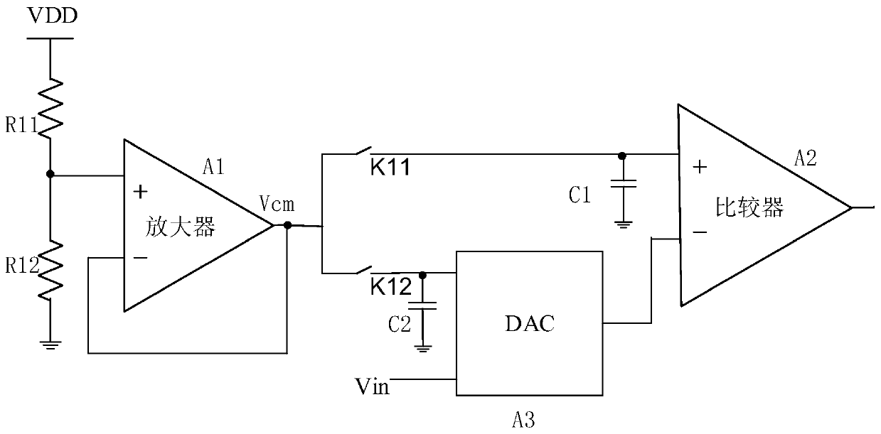
[0027] Such as figure 1 as shown, figure 1 It is a circuit diagram of a traditional comparator circuit in a DAC circuit, including the eleventh voltage dividing resistor R11, the twelfth voltage dividing resistor R12, the DC power supply VDD, the amplifier A1, the comparator A2, the DAC module A3, and the eleventh capacitor C11 , the twelfth capacitor C12, the eleventh switch K11 and the twelfth switch K12, one end of the eleventh voltage dividing resistor R11 is connected to the DC power supply VDD, and the other end of the eleventh voltage dividing resistor R11 is connected to the One end of the twelfth voltage-dividing resistor R12, the other end of the twelfth voltage-dividing resistor R12 is grounded, and the positive input end of the amplifier A1 is connected to the eleventh voltage-dividing resisto...
PUM
 Abstract
Description
Claims
Application Information
 - Generate Ideas
- Intellectual Property
- Life Sciences
- Materials
- Tech Scout
- Unparalleled Data Quality
- Higher Quality Content
- 60% Fewer Hallucinations
Browse by: Latest US Patents, China's latest patents, Technical Efficacy Thesaurus, Application Domain, Technology Topic, Popular Technical Reports.
© 2025 PatSnap. All rights reserved.Legal|Privacy policy|Modern Slavery Act Transparency Statement|Sitemap|About US| Contact US: help@patsnap.com