Ceramic composition
一种陶瓷组合物、组合物的技术,应用在稀土金属化合物、稀土金属氧化物/氢氧化物、可持续建筑等方向,能够解决白色LED颜色不均、透过率下降、耐热性差等问题,达到提高内量子效率、抑制发光效率的下降的效果
- Summary
- Abstract
- Description
- Claims
- Application Information
AI Technical Summary
Problems solved by technology
Method used
Image
Examples
preparation example Construction
[0110] The preparation method of the ceramic composition of the present invention is not particularly limited, but it can be obtained, for example, by firing a composition (precursor composition, ceramic precursor composition) containing a fluorescent material and lanthanum oxide (sintering treatment). .
[0111] As the fluorescent material, commercially available items may be used, or prepared products may be used. The method for producing the fluorescent material can be appropriately selected according to the type of fluorescent material, and is not particularly limited, and a commonly used method can be used.
[0112] For example, it can be obtained by heat-treating (firing, calcining) a fluorescent material source [for example, yttrium salt, aluminum salt, and if necessary, a rare earth element salt (cerium salt, etc.)] in the presence of oxygen.
[0113] In addition, the heat treatment temperature may be, for example, 500°C or higher (for example, 600 to 2000°C), prefera...
Embodiment 1
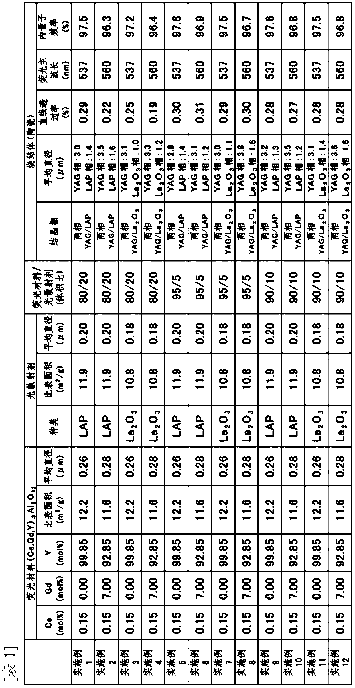
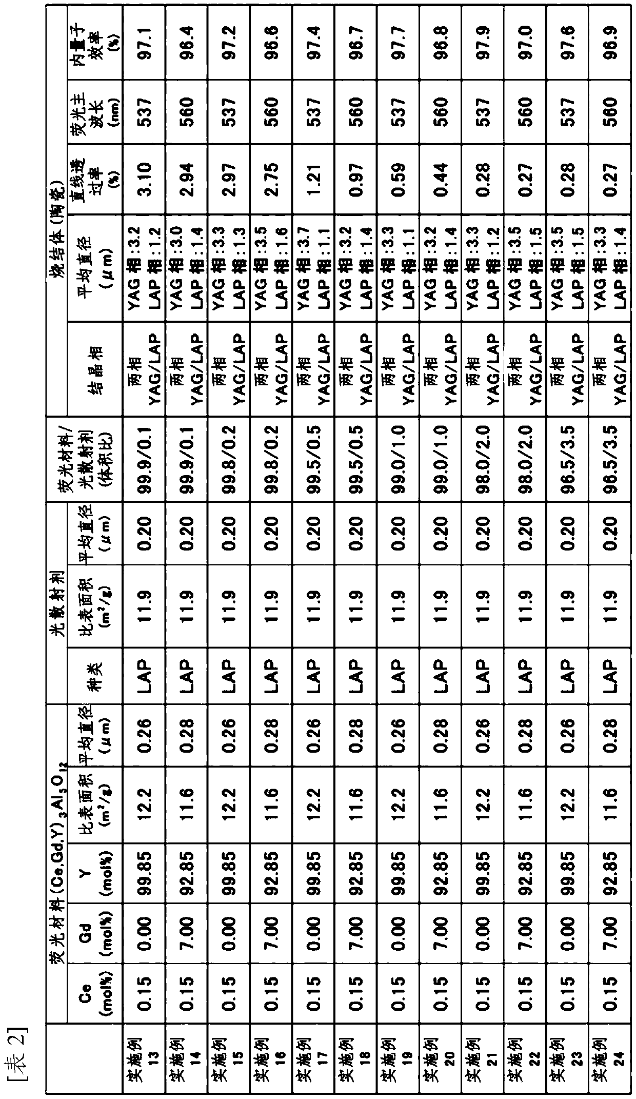
[0152] Embodiment 1: Ce:YAG+scattering source LAP
[0153] [Fluorescence material (Ce 0.15%:YAG)]
[0154] 14.98 L of 0.5 mol / L high-purity (rare earth elements are more than 99.99%, hereinafter the same) yttrium chloride aqueous solution, 0.02 L of 0.5 mol / L high-purity cerium nitrate aqueous solution, 25 L of 0.5 mol / L high Pure aluminum chloride aqueous solution is mixed to make a mixed solution composed of garnet (YAG).
[0155] A mixed solution composed of YAG was added dropwise at a rate of 1.5 L / min to 40 L of a 2 mol / L ammonium bicarbonate aqueous solution whose pH was adjusted to 8.2 using ammonia water. At this time, the mixed solution composed of YAG and the ammonium bicarbonate aqueous solution were simultaneously maintained at 32°C.
[0156]After the dropwise addition, aging at 32° C. for 48 hours, filtration and water washing were repeated 6 times to obtain a YAG precursor. The obtained YAG precursor was calcined at 1200° C. for 5 hours in the air and pulveri...
Embodiment 2
[0171] Embodiment 2: Ce: (Y, Gd) AG+scattering source LAP
[0172] Except for using the fluorescent material (Ce:(Y,Gd)AG) obtained by the following method as the fluorescent material in Example 1, molding and firing were carried out in the same manner as in Example 1 to obtain a sintered body (ceramic) .
[0173] As in Example 1, the obtained sintered body had a structure in which individual particles (single crystal particles) in micron units were closely aggregated (the width of the grain boundary was less than 1 nm), almost no voids were confirmed, and there were no impurities in the grain boundaries. In addition, it was confirmed that some crystal grains were grains with different contrasts, and were composed of two different substances.
[0174] Furthermore, the obtained sintered body was arranged on the blue LED, and the luminance in the vertical direction and at an angle of 45 degrees was compared using a luminance meter, and the luminance was about the same. From ...
PUM
| Property | Measurement | Unit |
|---|---|---|
| particle diameter | aaaaa | aaaaa |
| specific surface area | aaaaa | aaaaa |
| specific surface area | aaaaa | aaaaa |
Abstract
Description
Claims
Application Information
 - R&D
- Intellectual Property
- Life Sciences
- Materials
- Tech Scout
- Unparalleled Data Quality
- Higher Quality Content
- 60% Fewer Hallucinations
Browse by: Latest US Patents, China's latest patents, Technical Efficacy Thesaurus, Application Domain, Technology Topic, Popular Technical Reports.
© 2025 PatSnap. All rights reserved.Legal|Privacy policy|Modern Slavery Act Transparency Statement|Sitemap|About US| Contact US: help@patsnap.com


