High-grasping-vine vegetable waste collecting and transferring machine and operating method thereof
A transfer machine and vine technology, applied in the field of agricultural machinery, can solve the problems of automatic collection and transfer of vegetable waste tails, large pulling force, and difficulty in collection, etc., and achieve the effect of reducing collection and transfer costs, good effect, and convenient collection
- Summary
- Abstract
- Description
- Claims
- Application Information
AI Technical Summary
Problems solved by technology
Method used
Image
Examples
Embodiment 1
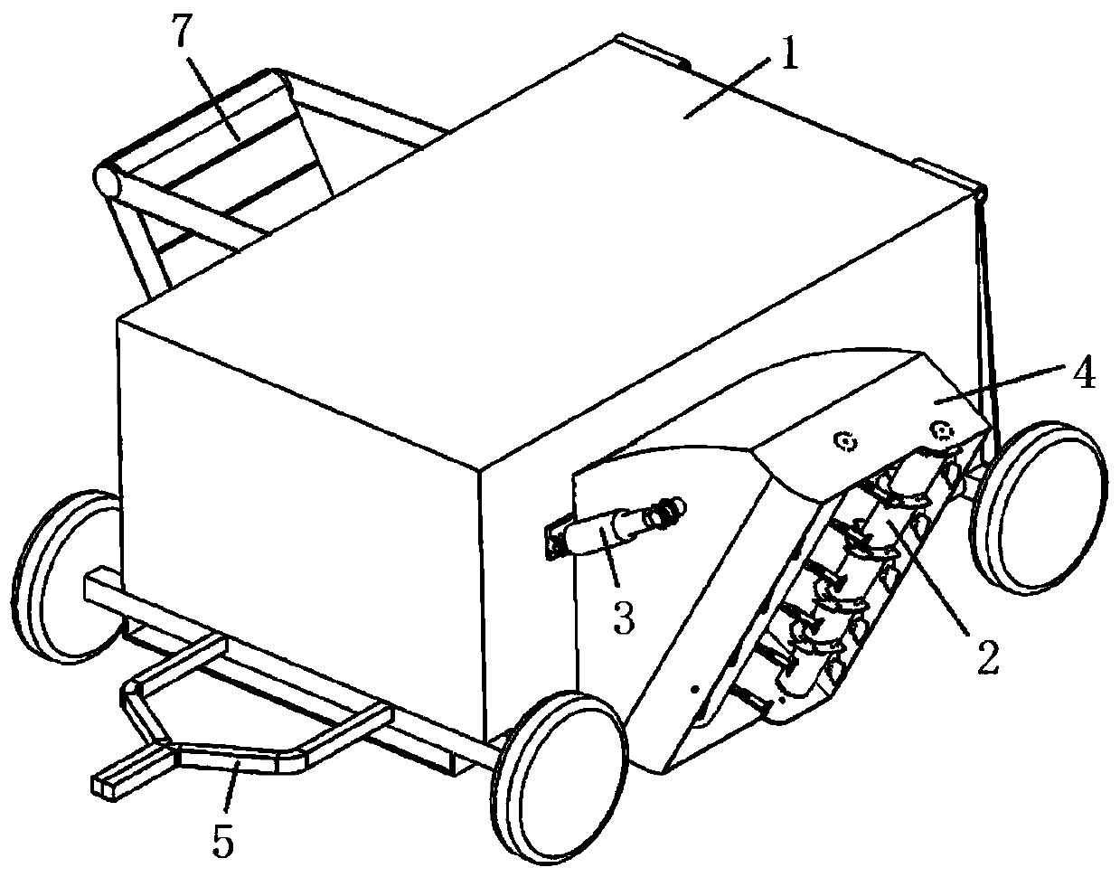
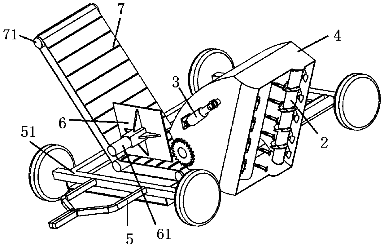
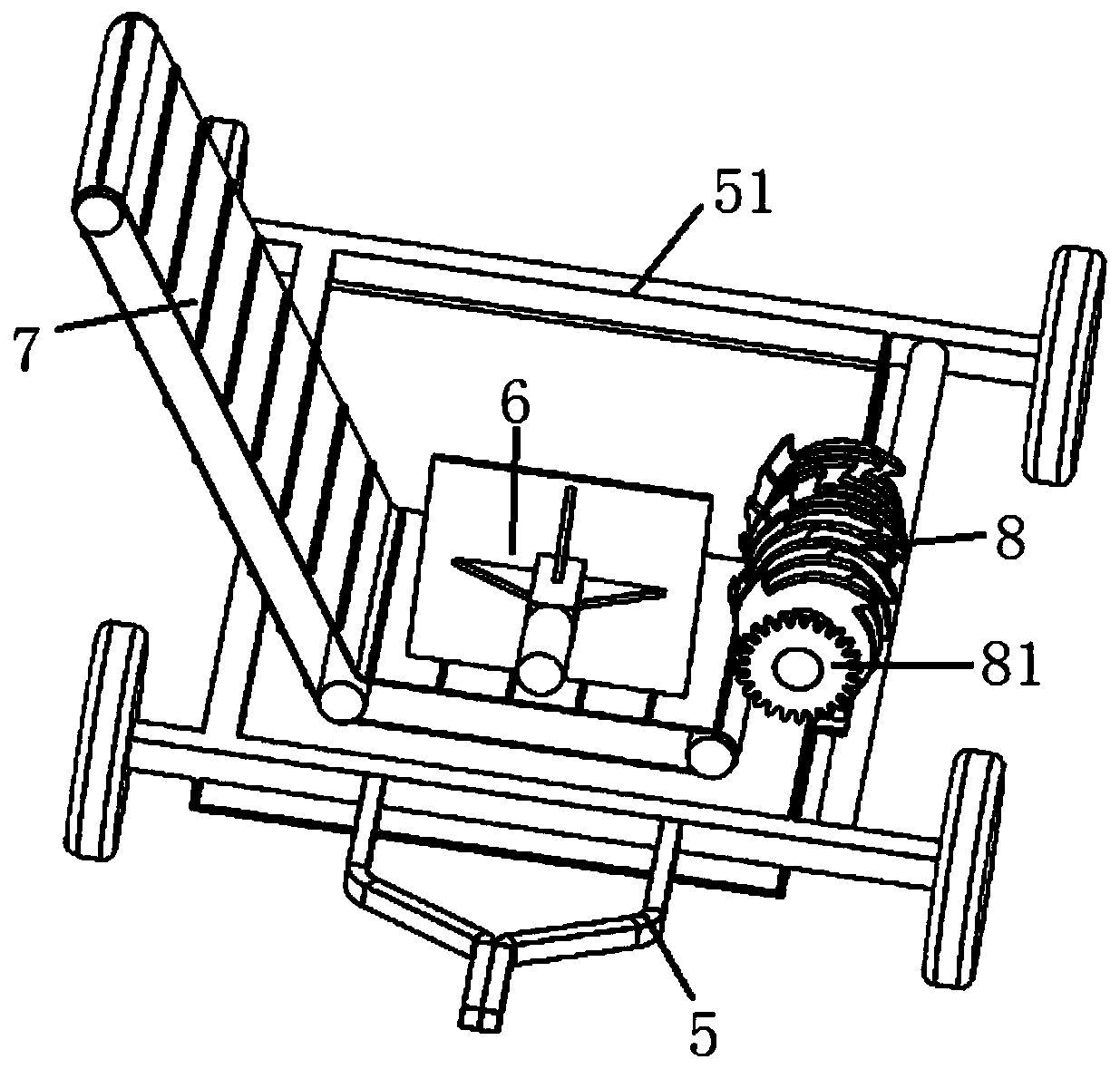
[0035] see figure 1 , figure 2 , image 3 , a high-winding vine vegetable waste tail vegetable collection and transfer machine, including a frame, a feeding assembly, a crushing assembly 8 and a conveying assembly, wherein the bottom of the frame is a rectangular plate-shaped chassis 51, and the surroundings of the chassis 51 are provided with rollers. The front end of chassis 51 is provided with U-shaped draw bar 5, and chassis 51 is provided with machine cover 1, and the top of machine cover 1 rear end side plate is hinged with top plate; Image 6 The feeding assembly is arranged on one side of the machine cover 1, and the feeding assembly includes a feeding roller 2 and a crushing roller 9 arranged obliquely in parallel. The feeding roller 2 rotates to wrap the material, and the crushing roller 9 rotates to interrupt the feeding The material attached to the material roller 2; the discharge port at the bottom of the feeding assembly is located in the hood 1;
[0036] see...
Embodiment 2
[0053] A compression mechanism is provided in the hood 1 on one side of the conveyor belt 7, and the compression mechanism includes an electric telescopic rod 61 and a pressing plate 6, wherein the fixed end of the electric telescopic rod 61 is fixedly connected to the inner wall of the side plate of the hood 1, and the pressing plate 6 Longitudinally fixed on the movable end of the electric telescopic rod, the bottom end of the pressing plate 6 is located above the inner section of the conveyor belt 7; during transfer in the middle, the picked up and crushed materials are pushed to the rear end of the machine cover 1 under the action of the pressing plate 6 Store and wait for the return of the transport vehicle to transport again to improve the transfer efficiency; the rest of the structure is the same as in Embodiment 1.
Embodiment 3
[0055] On the crushing roller 9, there are two rows of short blades 91 distributed along the axial direction, and the two rows of short blades 91 and two rows of long blades 92 are distributed in the shape of a "ten"; the short blades 91 are close to but not in contact with the spiral blade 21. ;The long knife on the crushing roller extends into the gap of the feeding roller to rotate and break the material, and the short knife cooperates with the spiral blade to break the material, ensuring that all the materials attached to the feeding roller can be broken and avoiding material winding and feeding Material roller affects operation; All the other structures are with embodiment 1.
PUM
 Abstract
Description
Claims
Application Information
 - R&D
- Intellectual Property
- Life Sciences
- Materials
- Tech Scout
- Unparalleled Data Quality
- Higher Quality Content
- 60% Fewer Hallucinations
Browse by: Latest US Patents, China's latest patents, Technical Efficacy Thesaurus, Application Domain, Technology Topic, Popular Technical Reports.
© 2025 PatSnap. All rights reserved.Legal|Privacy policy|Modern Slavery Act Transparency Statement|Sitemap|About US| Contact US: help@patsnap.com


