
Rubber band binding device of plastic bag

A strapping device and plastic bag technology, applied in the direction of strapping objects, strapping materials, packaging/bundling items, etc., can solve the problems of easy sagging, bending, folding down, rebound expansion of plastic bags, and easy loosening of plastic bags, etc., to achieve Saves the cost of binding, is not easy to break, and has the effect of simple structure

Inactive Publication Date: 2019-07-23
王秀来
View PDF5 Cites 1 Cited by
  • Summary
  • Abstract
  • Description
  • Claims
  • Application Information

AI Technical Summary

Problems solved by technology

[0005] The problem in Comparative Document 2 is: the product conveying manipulator only clamps one end of the plastic bag, while the other end hangs outside, and the part hanging outside will rebound, forming a bell mouth shape, that is, the place clamped by the manipulator is U-shaped Type, and the place not clamped by the manipulator, that is, the plastic bag on the side corresponding to the strapping mechanism will rebound and expand, and its end face is V-shaped
The existing problem is that the plastic bag delivery device (plastic bag feeding mechanism) is a conveyor belt, and when the conveyor belt transports the plastic bags to the strapping mechanism, the folded plastic bags are easy to fall apart.
Although the plastic bag in the flat state reduces the rebound during the bundling process, it is not easy to open into a V shape, but it is easy to sag, bend, and fold down

Method used


Image

  • Rubber band binding device of plastic bag
  • Rubber band binding device of plastic bag
  • Rubber band binding device of plastic bag

Examples


Embodiment 1

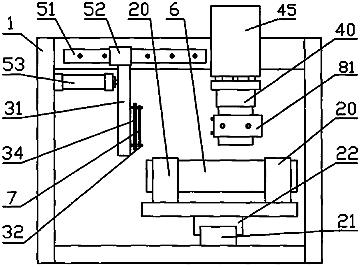
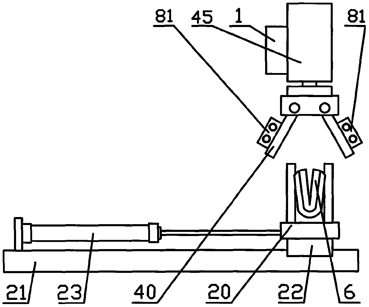
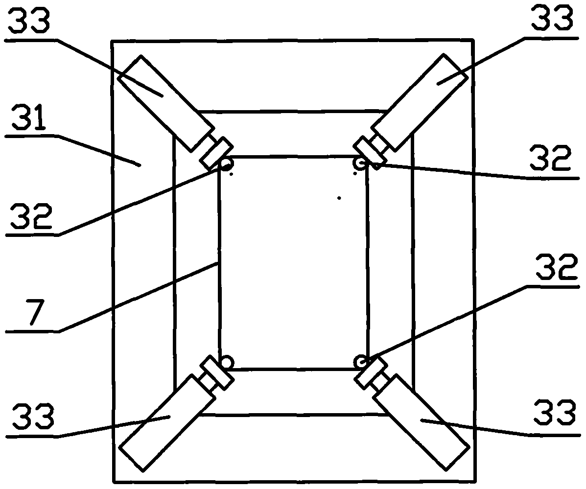
[0034] Embodiment one, such as Figure 1 to Figure 6 Shown: the relative movement mechanism 5 of embodiment one comprises guide rail 51, slide block 52, cylinder 53; A guide rail 51 is installed on the upper side of frame 1, and strapping mechanism 3 is slidably installed through slide block 52 below guide rail 51, in A cylinder 53 is connected between the strapping mechanism 3 and the frame 1; when the cylinder 53 works, the strapping mechanism 3 can be driven to perform a reciprocating linear motion relative to the bag clamping manipulator 40. Described binding mechanism 3 comprises support 31, strut 32, stretches out cylinder 33, as image 3 Shown: a square support 31 is set, and the middle part of the support 31 is provided with a square opening for enabling the plastic bag 6 to pass through; A strut 32 is respectively installed on the cylinder rod of 33. Suspended outward clamping bag mechanism 4 is a kind of bag clamping manipulator 40; Telescopic rod mechanism 8 is a ...

Embodiment 2

[0036] Embodiment two, such as Figure 8 , Figure 9 , Figure 10 Shown: the main difference of embodiment two is that the plastic bag feeding mechanism 2 of embodiment two is made of chain drive mechanism 24 and U-shaped clip 25, and telescopic rod mechanism 8 is made of square rail and slide block 84, cylinder 85. Such as Figure 8 Shown: a slide block 84 and a cylinder 85 are respectively installed on both sides of the bag clamping manipulator 40, and a wide-body square rail 83 is slidably installed on the slide block 84 respectively, so that the cylinder rod of the cylinder 85 is connected with the square rail 83 respectively, Described square rail 83 is a kind of wide body square rail, is exactly a kind of in fact. Such as Figure 9 Shown: the plastic bag delivery mechanism 2 of embodiment two comprises chain transmission mechanism 24 and U-shaped clip 25, and the plastic bag delivery mechanism that the embodiment two is made of chain transmission mechanism and U-shap...

Embodiment 3

[0039] Embodiment three, such as Figure 10 , Figure 11 , Figure 12 Shown: the main difference between the third embodiment and the first embodiment is that the plastic bag feeding mechanism 2 includes a turning frame 26, a turning part 27, a slider 22, a guide rail 21, and a cylinder 23. In the initial state, the turning frame 26 is Upright, that is, the opening of the overturning frame 26 faces upwards. When the plastic bag 6 is folded in the overturning frame 26, it is in a U-shaped upright state. When the overturning part 27 drives the overturning frame 26 to turn over about 90 degrees, it is formed Figure 11 In the state shown, the above-mentioned embodiment of the plastic bag feeding mechanism 2 has been disclosed in reference document 5, and reference can be made to a utility model patent entitled a packaging bag transfer device with the authorized announcement number CN207972864U. The plastic bag feeding mechanism of the third embodiment can directly transport the...


PUM


Abstract

The invention discloses a rubber band binding device of a plastic bag. The rubber band binding device comprises a machine frame, a vibration disc mechanism, a binding mechanism and a plastic bag feeding mechanism, and is characterized in that a suspension outer clamping mechanism is further arranged at the position, corresponding to the plastic bag feeding mechanism, of the plastic bag feeding mechanism, the suspension outer clamping mechanism comprises a bag clamping mechanical arm, and a telescopic rod mechanism is further arranged on the bag clamping mechanical arm. In the process of binding the plastic bag with a rubber band, the suspension outer clamping mechanism clamps one side of the plastic bag, the other side of the plastic bag is suspended outside, and the part which is suspended outside is easy to rebound and spread due to the fact that the clamping force of the bag clamping mechanism is lost, so that the opening amplitude of the rubber band needs to be increased or the rubber band with a large model is adopted. According to the rubber hand binding device, after a telescopic rod mechanism is adopted, the rebound plastic bag can be folded and leveled, and thus the breakage rate of the rubber band is reduced, and the bundling cost is reduced.

Description

technical field [0001] The invention relates to a rubber band binding device for plastic bags. Background technique [0002] The plastic bags automatically produced by the bag making machine, in order to facilitate storage, sales and use, these plastic bags are also automatically folded many times by a plastic bag folding machine, and finally folded into long strips, and the plastic bags folded into long strips are The end surface is U-shaped, because the folded plastic bag is elastic and easy to rebound and scatter, so it is necessary to put an elastic ring-shaped rubber band in the middle of the folded plastic bag, which is the so-called rubber band binding of the plastic bag. . [0003] Authorized notification number CN208070086U discloses an automatic strapping machine (hereinafter referred to as reference document 1), which mainly includes: a main material feeding mechanism (ie, a plastic bag feeding mechanism), an auxiliary material feeding mechanism (vibrating plate ...

Claims


Application Information

Patent Timeline
IPC IPC(8): B65B27/08B65B13/18B65B13/02
CPCB65B13/022B65B13/18B65B27/08
Inventor 王秀来
Owner 王秀来
Learn More