
Compact Antennas and Mobile Terminals

A mobile terminal, compact technology, applied in the direction of antenna, resonant antenna, antenna array powered separately, etc., can solve the problems of poor signal coverage in the direction of the screen or rear cover, affect the volume of the antenna terminal, and the large size of the antenna hardware, etc., to improve The effects of antenna space coverage, ease of antenna installation, and hardware cost reduction

Active Publication Date: 2021-08-31
ONEPLUS TECH SHENZHEN
View PDF6 Cites 0 Cited by
  • Summary
  • Abstract
  • Description
  • Claims
  • Application Information

AI Technical Summary

Problems solved by technology

[0003] The millimeter-wave antenna in the first structure only has a patch array, and the space coverage is at a disadvantage compared with the millimeter-wave antenna in the second structure, and in mobile terminals, it is easy to cause poor signal coverage in the direction of the screen or back cover; the second In the millimeter-wave antenna array in the two structures, although the multiple antennas and the corresponding parasitic units in the millimeter-wave antenna array improve the spatial coverage, the hardware size of the antenna is large, and the use of the antenna tends to be smaller and smaller In the situation of modernization and refinement, a large antenna is not only not conducive to installation and use, but also affects the volume of the terminal where the antenna is located.

Method used


Image

  • Compact Antennas and Mobile Terminals
  • Compact Antennas and Mobile Terminals
  • Compact Antennas and Mobile Terminals

Examples


Embodiment 1

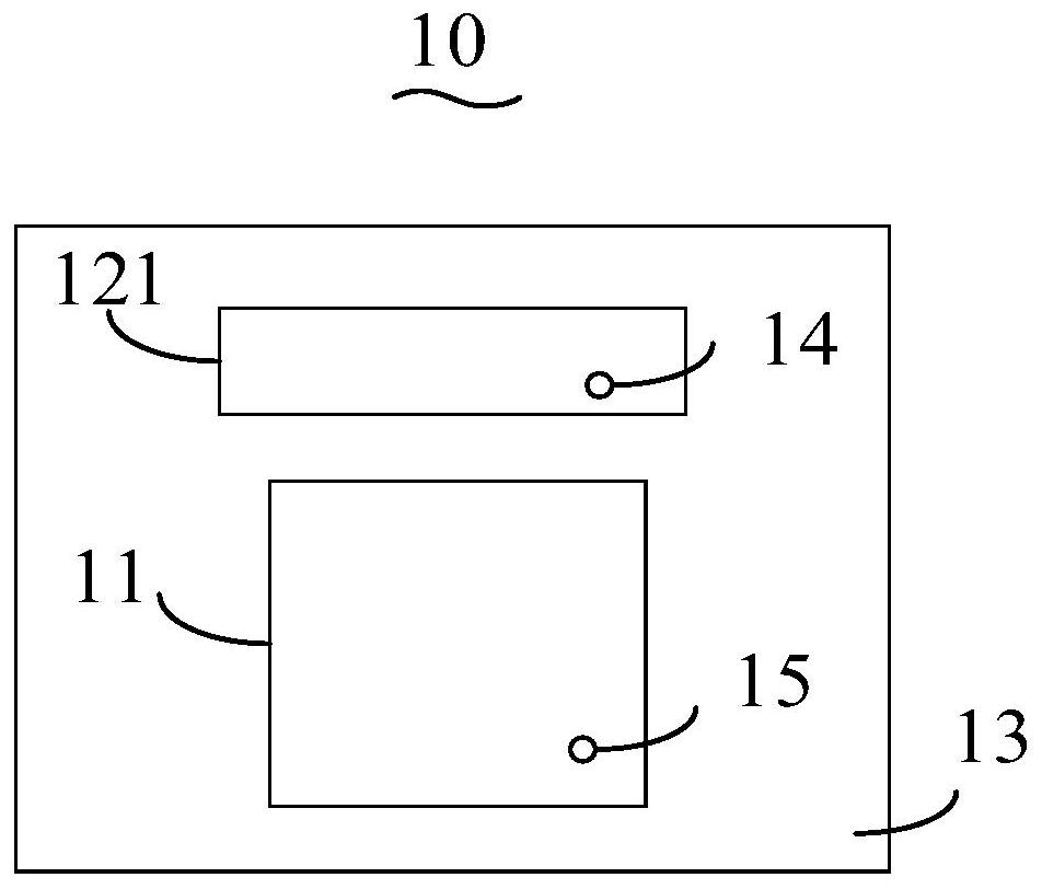
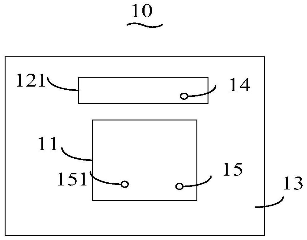
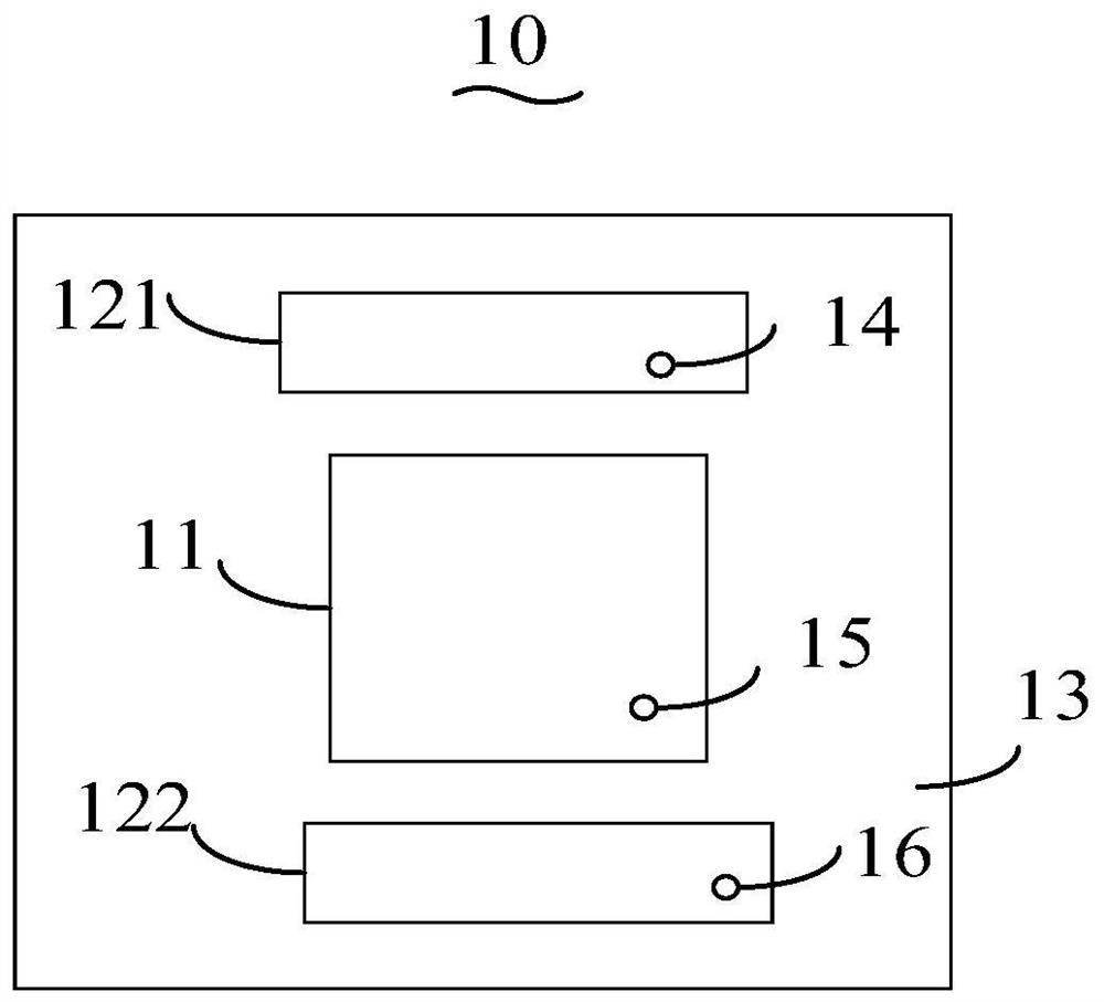
[0039] With the continuous development of wireless communication technology, various communication systems have higher and higher requirements for broadband. In order to expand the bandwidth of the antenna, at least one parasitic unit is usually set around the antenna. The at least one parasitic unit cannot exist independently. Corresponding antennas coexist and are electromagnetically coupled with the corresponding antennas to achieve parasitic functions, such as reducing the operating frequency of the antennas, expanding the bandwidth of the antennas, and forming multiple frequency bands.

[0040] The parasitic units are arranged around the corresponding antenna and close to the corresponding antenna, and can be arranged in a predetermined manner. The specific position of the parasitic unit is set according to the radiation performance of the antenna, for example, the maximum impedance bandwidth between it and the corresponding antenna shall prevail, and the coupling distance...


PUM


Abstract

The invention discloses a compact antenna and a mobile terminal. The compact antenna includes: a predetermined antenna, and at least one parasitic unit corresponding to the predetermined antenna; a feeding point is set in the at least one parasitic unit, and through the The feeding point feeds the corresponding parasitic unit so that the parasitic unit has an independent antenna function. The technical scheme of the invention can reuse the parasitic unit in the existing antenna, so that the parasitic unit has radio frequency function, improves the space coverage and reduces the size of the antenna.

Description

technical field [0001] The present invention relates to the technical field of antennas, in particular to a compact antenna and a mobile terminal. Background technique [0002] The fifth generation (5G) communication technology includes the millimeter wave frequency band (24250MHZ ~ 52600MHZ), which may be extended to higher frequency bands for wireless communication. In antenna engineering, the parasitic unit can be used for the purpose of lowering the operating frequency, widening the frequency band and multi-band. In the existing millimeter-wave antennas, there are two structures: the first is a patch array with parasitic elements, and the second is a patch array with parasitic elements and an independent dipole array. [0003] The millimeter-wave antenna in the first structure only has a patch array, and the space coverage is at a disadvantage compared with the millimeter-wave antenna in the second structure, and in mobile terminals, it is easy to cause poor signal cove...

Claims


Application Information

Patent Timeline
Patent Type & Authority Patents(China)
IPC IPC(8): H01Q1/50H01Q5/378H01Q5/50
CPCH01Q5/378H01Q5/50H01Q1/50H01Q19/005H01Q5/385H01Q21/08H01Q9/0407H01Q9/30
Inventor 钟永卫吴镇仲
Owner ONEPLUS TECH SHENZHEN
Learn More