
Spin riveting equipment for bottom of pulsator drum of washing machine and spin riveting method of spin riveting equipment

A washing machine and tube bottom technology, which is applied in the washing machine pulsator tube bottom spin riveting equipment and its spin riveting field, can solve the problems affecting product appearance quality, affecting product quality, uneven pressing, etc., and achieve reliability and uniformity High performance, compact structure, ensuring the effect of uniform motion

Pending Publication Date: 2019-07-26
WUXI IDO SCI & TECH CO LTD
View PDF0 Cites 6 Cited by
  • Summary
  • Abstract
  • Description
  • Claims
  • Application Information

AI Technical Summary

Problems solved by technology

[0002] In the prior art, the riveting method for the bottom of the pulsator drum of the washing machine requires flanging the pulsator drum and the bottom of the drum first, and then rotating and rolling the wheels with notches to rotate and fasten the two layers of materials. Then, they are riveted together by compaction with the blanking wheel. The disadvantage of this method is that the uneven pressing due to the uneven force during the blanking, the slow speed of the blanking and the low efficiency, and it is easy to cause misalignment during the riveting. affect product quality
[0003] In the prior art, the equipment for riveting the inner cylinder and the upper and lower covers also needs to fold the inner cylinder and the connected upper and lower covers together first, and then fix them through the upper and lower flanges of the equipment. The flanges of the upper and lower covers apply radial force to realize the pressing with the inner cylinder. The inner cylinder is a thin-walled cylindrical structure. When the force is applied up and down at the same time, the two ends will be slightly deformed inward, which will affect the appearance quality of the product.

Method used


Image

  • Spin riveting equipment for bottom of pulsator drum of washing machine and spin riveting method of spin riveting equipment
  • Spin riveting equipment for bottom of pulsator drum of washing machine and spin riveting method of spin riveting equipment
  • Spin riveting equipment for bottom of pulsator drum of washing machine and spin riveting method of spin riveting equipment

Examples


Embodiment Construction

[0049] The specific embodiments of the present invention will be described below in conjunction with the drawings.

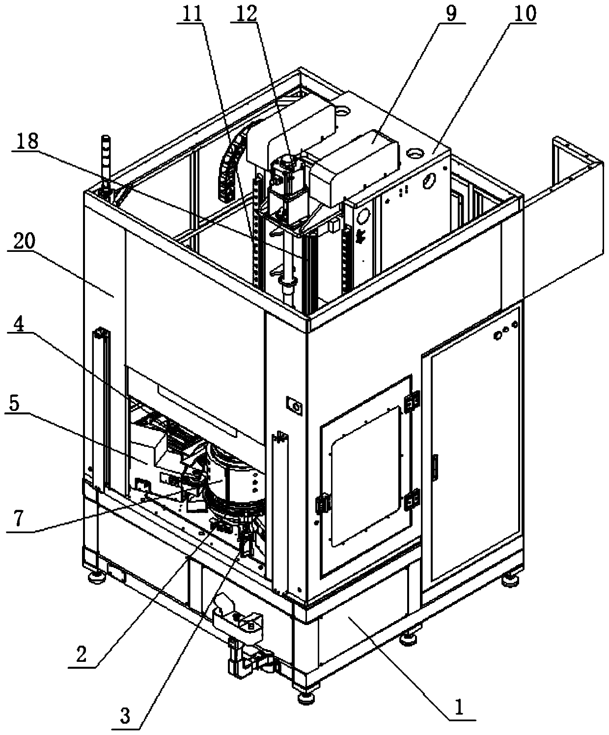
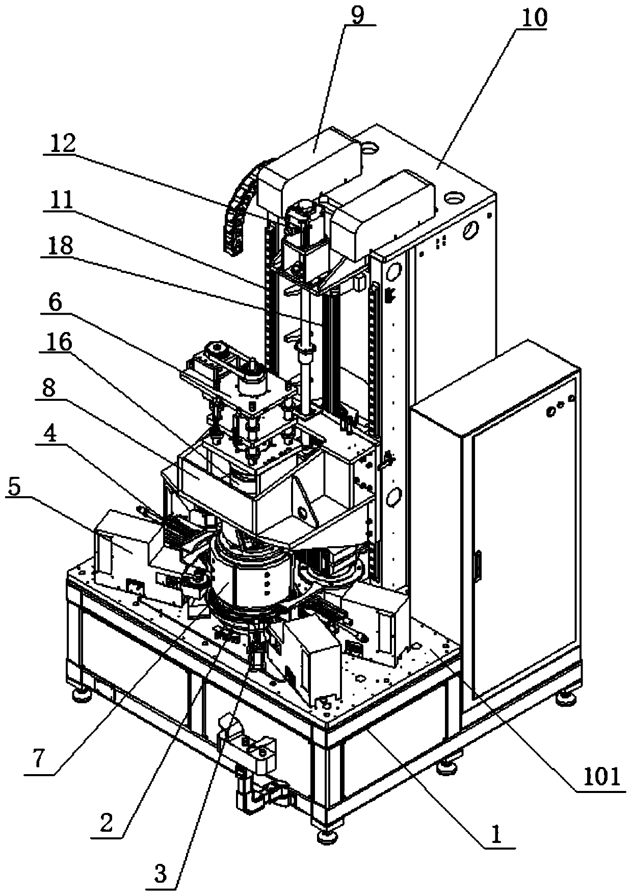
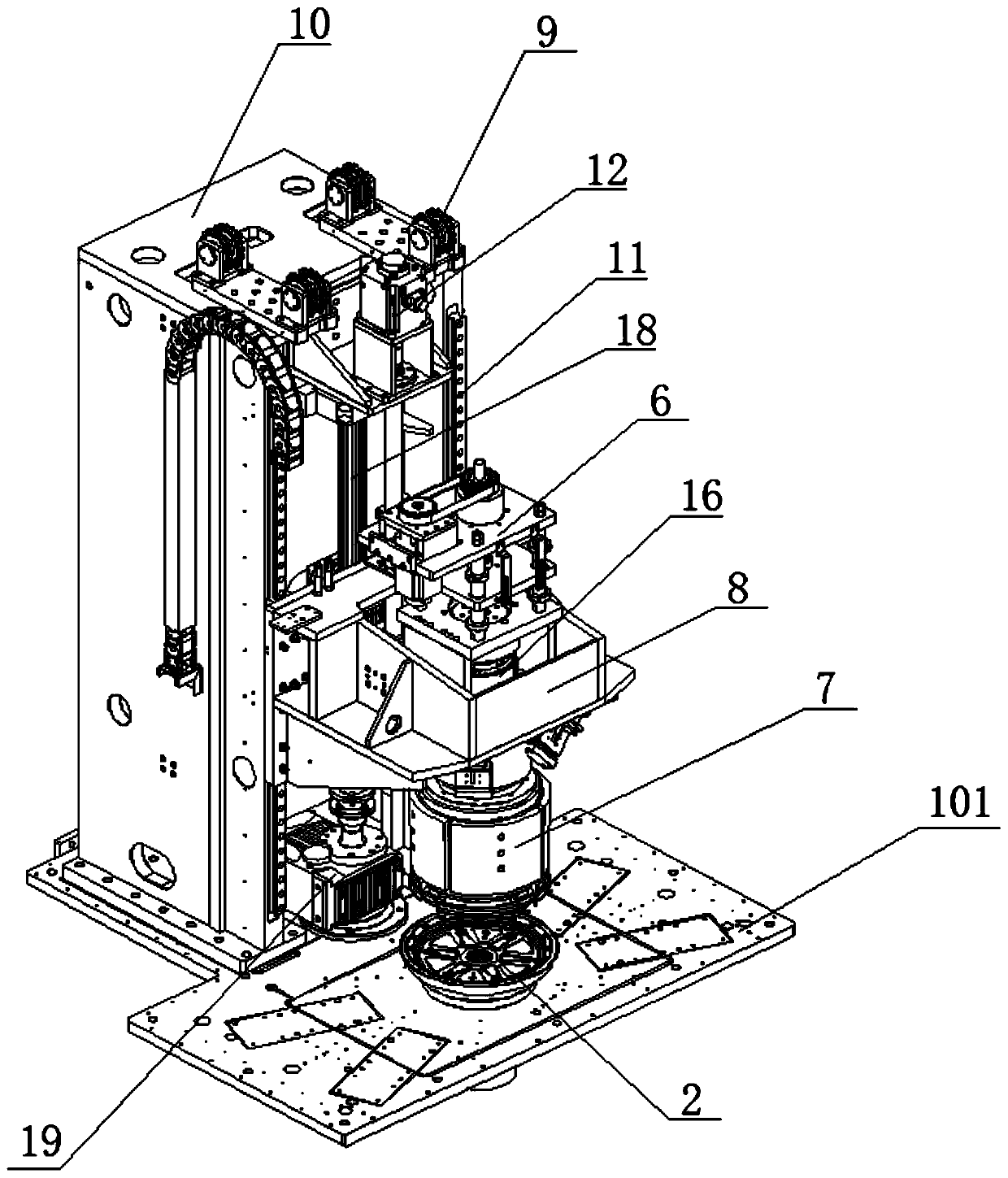
[0050] Such as figure 1 , figure 2 , image 3 with Figure 4 As shown, the washing machine pulsator drum bottom spin riveting equipment of this embodiment includes a frame 1, a working platform 101 is installed on the top, and a "┏┓"-shaped counterweight box 10 is installed on the rear side of the upper surface of the working platform 101. A guide rail 11 is installed on the front side. The guide rail 11 is installed with a supporting mold assembly 6 that slides along it. The supporting mold assembly 6 is driven by a servo motor 12 mounted on the top of the counterweight box 10, and is driven by a chain and a The counterweight 15 installed in the heavy box 10 is connected, and the lower part of the mold supporting assembly 6 is installed with a mold core 7; the main motor 19 is installed on the working platform 101 directly under the counterweight box 10, and its o...


PUM


Abstract

The invention relates to spin riveting equipment for the bottom of a pulsator drum of a washing machine and a spin riveting method of the spin riveting equipment. The spin riveting equipment comprisesa rack and a work platform arranged at the top, wherein a weight box is mounted on the rear side of the work platform, a mold propping assembly driven by a servo motor to move vertically is arrangedon a guide rail on the front side surface of the work platform, and a mold core is mounted at the lower part of the mold propping assembly; a profiling plate is mounted on the work platform under themold core, and a clamping assembly, a positioning assembly and multiple spin riveting assemblies are distributed in the circumferential direction of the profiling plate; a main motor is mounted underthe weight box, and an output shaft of the main motor drives the mold core and the profiling plate to rotate together under driving of a spline shaft and a belt. The drum body is pre-positioned from the outside by adopting the clamping assembly and the positioning assembly and then is supported from the inside by the mold propping assembly and the mold core, finally, spin riveting connection of the body and the bottom of the pulsator drum of the washing machine is realized under the action of the main motor and the spin riveting assemblies, the spin riveting efficiency is high, and spin riveting press fit quality is good.

Description

Technical field [0001] The invention relates to the technical field of washing machine assembly equipment, in particular to a washing machine pulsator barrel bottom spin riveting device and a spin riveting method. Background technique [0002] In the prior art, for the riveting method of the bottom of the washing machine pulsator drum, the pulsator drum and the bottom of the drum need to be flanged first, and then the two layers of material pieces are rotated and buckled by rotating and rolling through a wheel with notches. Then press the blanking wheel to compact and riveting together. The disadvantage of this method is that the uneven force during blank blanking leads to uneven pressing, slow blanking speed and low efficiency, and it is easy to cause misalignment pressing during spin riveting. Affect product quality. [0003] In the prior art, the equipment for riveting the inner cylinder and the upper and lower covers also requires the inner cylinder and the connected upper and...

Claims


Application Information

Patent Timeline
Patent Type & Authority Applications(China)
IPC IPC(8): B21D39/03B21D43/00B21D55/00
CPCB21D39/031B21D43/003B21D55/00
Inventor 张宁峰
Owner WUXI IDO SCI & TECH CO LTD
Learn More