
Partially-assembled pile support buttressed retaining wall

A prefabricated and retaining wall technology, applied in the field of retaining walls, can solve the problems of long construction period, uneven settlement of foundation, difficult construction, etc. Effect

Active Publication Date: 2019-07-26
LANZHOU UNIVERSITY OF TECHNOLOGY
View PDF9 Cites 2 Cited by
  • Summary
  • Abstract
  • Description
  • Claims
  • Application Information

AI Technical Summary

Problems solved by technology

However, the traditional buttress-type retaining wall relies on the earth pressure on the wall heel plate on the side of the filling to provide the anti-overturning moment. In the filling project, the size of the heel plate needs to be made very large to ensure The stability of the soil on one side of the square makes it difficult to construct such a retaining structure in a site with limited space. Moreover, traditional buttress retaining walls are often plagued by uneven settlement of the foundation
[0003] Aiming at the shortcoming that the traditional buttress-type retaining wall is easily restricted by site conditions, the patents with the patent announcement number CN204282395U and CN202730795U disclose the pile-buttress-type retaining wall, and the site conditions are reduced by setting piles under the wall. Effects on retaining walls
However, since the filling soil is still located on the side of the wall heel with buttresses, the problem of too large wall heel plate cannot be well solved, and due to this structural arrangement, the pile body cannot play a good role in resisting uplift. cause material waste
In addition, the traditional buttress retaining wall has a long construction period and complex on-site construction technology, which greatly limits the application of this retaining structure in retaining engineering

Method used


Image

  • Partially-assembled pile support buttressed retaining wall
  • Partially-assembled pile support buttressed retaining wall
  • Partially-assembled pile support buttressed retaining wall

Examples


Embodiment Construction

[0022] The following will clearly and completely describe the technical solutions in the embodiments of the present invention with reference to the accompanying drawings in the embodiments of the present invention. Obviously, the described embodiments are only some, not all, embodiments of the present invention. Based on the embodiments of the present invention, all other embodiments obtained by persons of ordinary skill in the art without making creative efforts belong to the protection scope of the present invention.

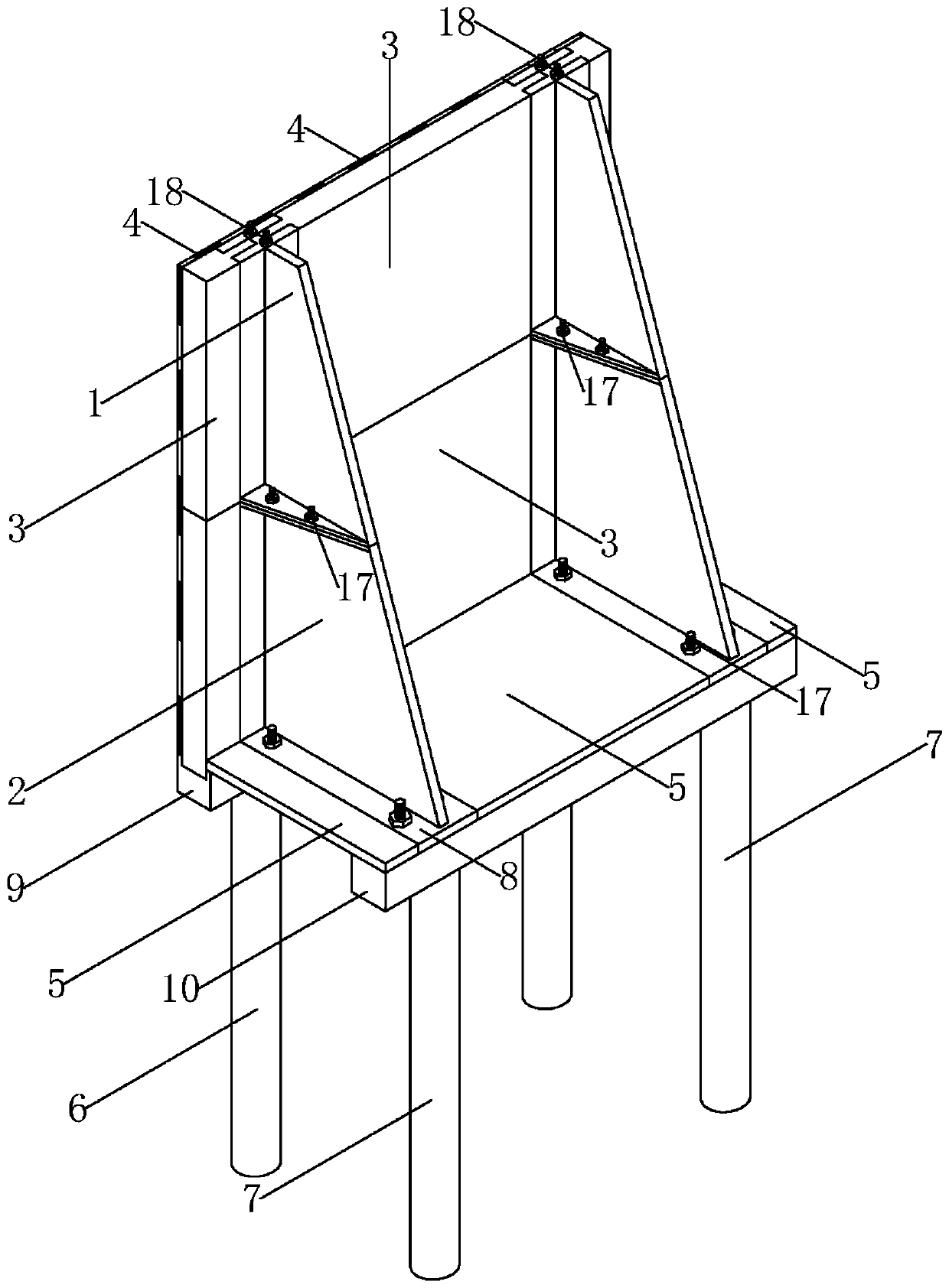
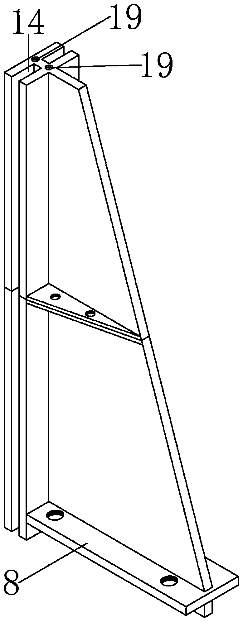
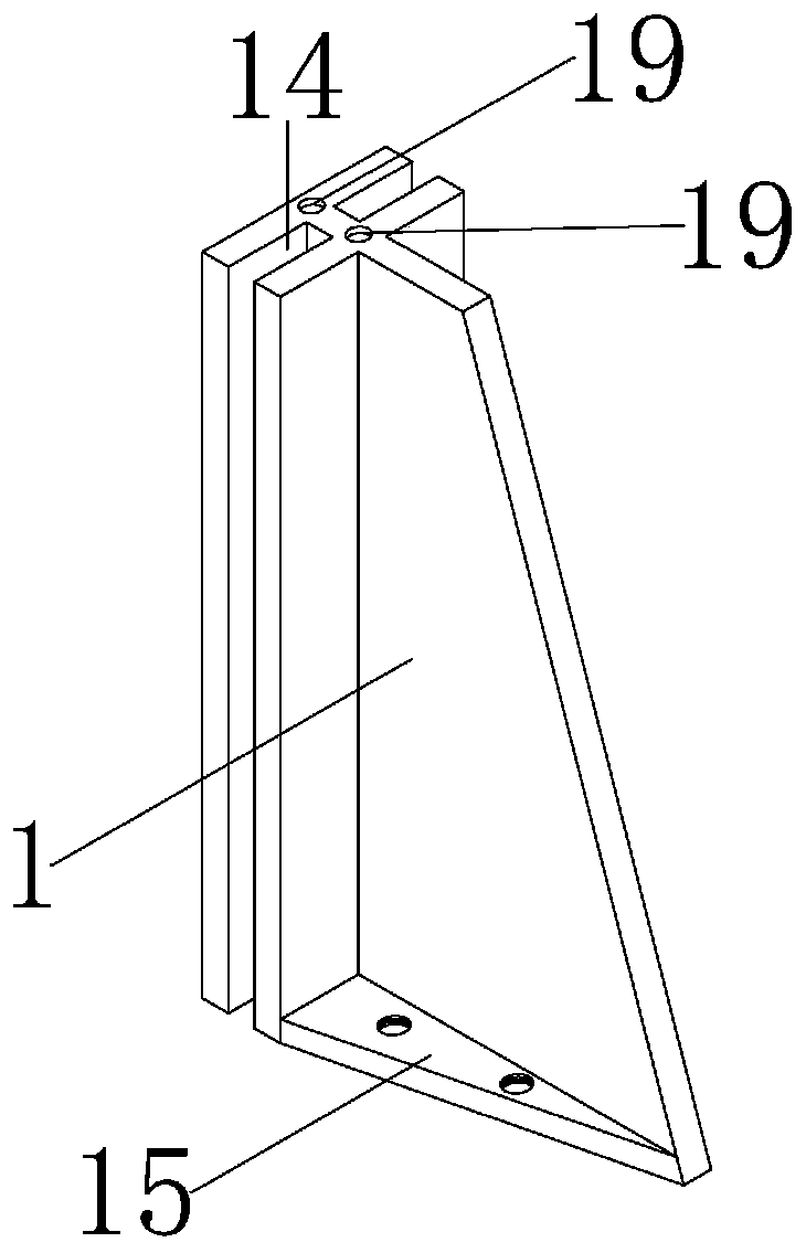
[0023] Such as Figure 1-Figure 6 As shown, this specific embodiment adopts the following technical scheme: it includes an upper special-shaped column 1, a lower special-shaped column 2, a wall panel 3, a high-strength fiber plate 4, a bottom plate 5, an uplift pile 6, a compression pile 7, and a bottom backing plate 8 , the first bottom beam 9, the second bottom beam 10, the connecting beam 11, the first slot 12, the second slot 13, the third slot 14, the fir...


PUM


Abstract

The invention discloses a partially-assembled pile support buttressed retaining wall, and belongs to the technical field of retaining walls. A lower foreign-shaped column is fixed into a second clamping groove in a connecting beam, and the lower part of the lower foreign-shaped column is provided with a bottom base plate which is connected with the connecting beam through bolts; a first stiffeningrib is arranged on the lower part of an upper foreign-shaped column, a second stiffening rib is arranged on the upper part of the lower foreign-shaped column, and the first stiffening rib and the second stiffening rib are fixedly connected through bolts; a wall face plate is connected with the upper foreign-shaped column and the lower foreign-shaped column through a first clamping groove and a third clamping groove; and the two ends of a bottom plate are lapped on a first bottom beam and a second bottom beam, and steel bars anchored on a lower pile body in a full-length mode are arranged on the first bottom beam. The retaining wall is built in the mode that prefabricated parts are assembled on site, the site construction difficulty can be lowered, the construction period is shortened, andgood economic and social benefits are achieved.

Description

technical field [0001] The invention relates to a partially assembled pile buttress retaining wall, which belongs to the technical field of retaining walls. Background technique [0002] The buttress retaining wall is a retaining structure with simple structure, small wall section and light weight. However, the traditional buttress-type retaining wall relies on the earth pressure on the wall heel plate on the side of the filling to provide the anti-overturning moment. In the filling project, the size of the heel plate needs to be made very large to ensure The stability of the soil on one side of the square makes it difficult for this retaining structure to be constructed in a narrow space. Moreover, traditional buttress retaining walls are often plagued by uneven settlement of the foundation. [0003] Aiming at the shortcoming that the traditional buttress-type retaining wall is easily restricted by site conditions, the patents with the patent announcement number CN20428239...

Claims


Application Information

Patent Timeline
IPC IPC(8): E02D29/02E02D27/12
CPCE02D27/12E02D29/0266
Inventor 叶帅华樊黎明叶炜钠
Owner LANZHOU UNIVERSITY OF TECHNOLOGY
Learn More