Exhaust gas recirculation (EGR) engine waste heat recovery system and control method thereof

A technology of engine waste heat and recovery system, applied in engine components, combustion engines, machines/engines, etc., can solve problems such as complex layout, and achieve the effect of improving recovery efficiency and simple structure

Pending Publication Date: 2019-07-26
DONGFENG COMML VEHICLE CO LTD
View PDF1 Cites 1 Cited by
  • Summary
  • Abstract
  • Description
  • Claims
  • Application Information

AI Technical Summary

Problems solved by technology

[0007] 3. The layout of the whole system is relatively complicated, and ...

Method used


Image

  • Exhaust gas recirculation (EGR) engine waste heat recovery system and control method thereof

Examples


Embodiment 1

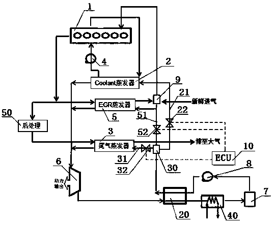
[0038] see figure 1 , a waste heat recovery system for an EGR engine, comprising an engine 1, a cooling water evaporator 2, an exhaust gas evaporator 3, an EGR evaporator 5, a liquid storage tank 7, a working medium pump 8, an EGR mixer 9, and a regenerator 20. The cooling water inlet of the cooling water evaporator 2 is connected with the cooling water outlet of the engine 1, the cooling water outlet of the cooling water evaporator 2 is connected with the cooling water inlet of the engine 1 through the cooling water pump 4, and the exhaust gas evaporator 3 The tail gas inlet is connected with the exhaust port of the engine 1 through the post-processing device 50, the tail gas outlet of the tail gas evaporator 3 is connected with the atmosphere, the EGR inlet of the EGR evaporator 5 is connected with the exhaust port of the engine 1, and the EGR evaporates The EGR outlet of the device 5 is connected with the intake port of the engine 1 through the EGR mixer 9, and the working ...


PUM


Abstract

An exhaust gas recirculation (EGR) engine waste heat recovery system comprises a cooling water evaporator, a tail gas evaporator and an EGR evaporator, wherein a working medium inlet of the cooling water evaporator, a working medium inlet of the tail gas evaporator and a working medium inlet of the EGR evaporator communicate with an outlet of a liquid storage tank respectively through a first pipeline, a second pipeline and a third pipeline; an inlet of the liquid storage tank communicates with a working medium outlet of the cooling water evaporator, a working medium outlet of the tail gas evaporator and a working medium outlet of the EGR evaporator through an expansion machine; and the first pipeline, the second pipeline and the third pipeline are provided with a first control valve, a second control valve and a third control valve respectively. The control method includes the step that when a vehicle is in stable or variable working conditions, an electronic control unit (ECU) controls the opening degree of each control valve according to cooling water waste heat energy, tail gas waste heat energy and EGR waste heat energy data. The system not only significantly improves the recovery efficiency of engine waste heat, but also is simple in structure, and facilitates heat management.

Description

technical field [0001] The invention belongs to the field of waste heat recovery of internal combustion engines, and in particular relates to a waste heat recovery system of an EGR engine and a control method thereof, which are suitable for improving the thermal efficiency of the engine. Background technique [0002] With the increase of car ownership, the energy consumed by cars is also increasing. At present, the combustion efficiency of automobile engines has reached a very high level, but its effective thermal efficiency is less than 50%. Nearly 1 / 3 of the total fuel energy is lost through exhaust gas energy, and about 20% or more of the total fuel energy enters cooling system. If this part of waste heat can be recovered and utilized in an effective way, it will play an important role in improving the fuel utilization rate of automobiles. [0003] At present, there are energy storage technology, turbo compounding, turbo power generation, thermoelectric power generation...

Claims


Application Information

Patent Timeline
IPC IPC(8): F02G5/04F02M26/13
CPCF02G5/04F02M26/13F02G2260/00Y02T10/12
Inventor 赵艳婷殷勇米娇
Owner DONGFENG COMML VEHICLE CO LTD
Why Eureka
Try Eureka