

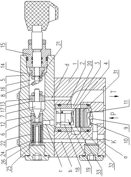
Pilot operated compound relief valve
A technology of pilot relief valve and pilot valve, which is applied in valve details, safety valves, balance valves, etc., can solve problems affecting the performance of pilot relief valves, failure of hydraulic power compensation, failure of main spool movement, etc. Achieve the effects of preventing motion failure, reducing hydraulic power, and increasing viscous damping
- Summary
- Abstract
- Description
- Claims
- Application Information
AI Technical Summary
Problems solved by technology
Method used
Image

Examples
Embodiment Construction
[0019] In order to make the object, technical solution and advantages of the present invention clearer, the present invention will be further described in detail below in conjunction with the accompanying drawings and embodiments. It should be understood that the specific embodiments described here are only used to explain the present invention, not to limit the present invention.
[0020] Such as figure 1 As shown, the pilot relief valve provided by the present invention is improved based on the "Pilot Hydraulic Pressure Relief Valve" published in the Chinese invention patent application number 201510259603.8. Specifically, the pilot relief valve in the present invention adopts a two-stage concentric structure. Compared with the three-stage concentric structure, the valve port area gradient of the pilot relief valve with the two-stage concentric structure is larger than that of the three-stage concentric structure. sensitive. The pilot-operated relief valve includes two par...
PUM
 Abstract
Description
Claims
Application Information