
Antenna servo system calibration method based on coordinate rotation

A technology of servo system and coordinate rotation, applied in the field of antenna servo system calibration based on coordinate rotation, can solve the problem of high cost, achieve low cost, save hardware and manpower, and reduce design and use costs

Active Publication Date: 2019-07-26
NO 54 INST OF CHINA ELECTRONICS SCI & TECH GRP
View PDF5 Cites 2 Cited by
  • Summary
  • Abstract
  • Description
  • Claims
  • Application Information

AI Technical Summary

Problems solved by technology

[0006] d) Calibration of the moving carrier antenna requires the use of special instruments such as level, theodolite, optical telescope, etc., and the cost is relatively high

Method used


Image

  • Antenna servo system calibration method based on coordinate rotation
  • Antenna servo system calibration method based on coordinate rotation
  • Antenna servo system calibration method based on coordinate rotation

Examples


Embodiment 1

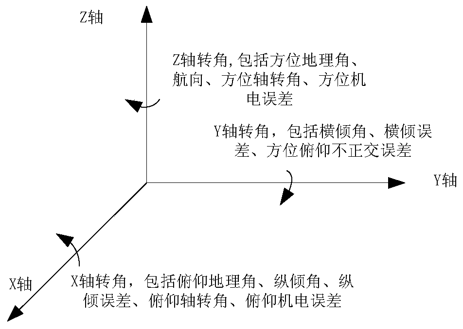
[0038] Taking the A-E (azimuth-elevation) two-axis pedestal antenna as an example, the calibration method of the antenna includes the following steps:

[0039] (1) A-E (azimuth-pitch) two-axis pedestal antenna system error analysis

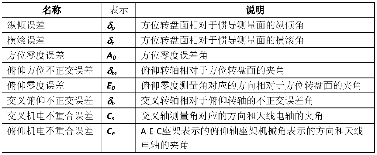
[0040] Analyze the systematic errors of the A-E (azimuth-pitch) two-axis pedestal antenna, mainly including the pitch error, roll error of the antenna azimuth turntable, the mechanical zero degree of the azimuth axis, the non-orthogonal error of the azimuth axis and the pitch axis, and the pitch mechanical error. The misalignment error between the axis and the electric axis of the antenna, the misalignment error between the azimuth mechanical axis and the electric axis of the antenna, the error expression is shown in the table below;

[0041]

[0042] (2) Determine the rotation matrix of the shaft angle and system error according to the shaft relationship

[0043] A-E (azimuth-pitch) two-axis pedestal antenna axis coordinate relationship diagr...

Embodiment 2

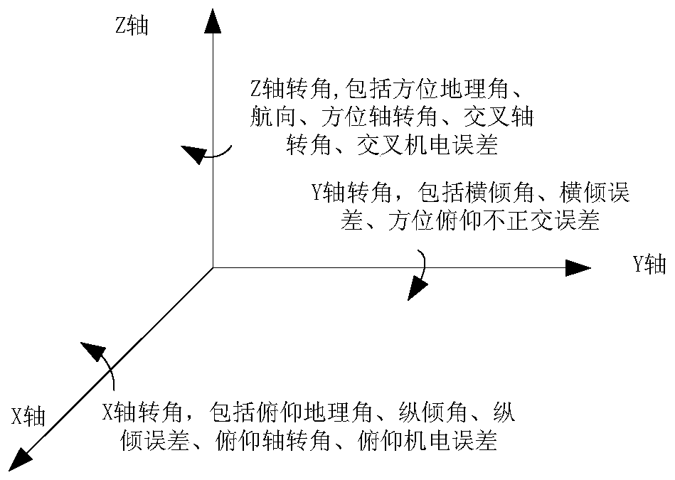
[0068] Taking the A-E-C (azimuth-elevation-cross) three-axis pedestal antenna as an example, the calibration method of the antenna includes the following steps:

[0069] (1) System Error Analysis of A-E-C (Azimuth-Elevation-Cross) Triaxial Mount Antenna

[0070] Analyze the systematic errors of the A-E-C (azimuth-pitch-cross) three-axis mount antenna, mainly including the pitch error and roll error of the antenna azimuth turntable, the mechanical zero degree of the azimuth axis, the non-orthogonal error of the azimuth axis and the pitch axis, The mechanical zero of the pitch axis, the non-orthogonal error between the pitch axis and the cross axis, the non-coincidence error between the cross mechanical axis and the antenna electrical axis, and the non-coincidence error between the pitch mechanical axis and the antenna electrical axis, the error expression is shown in the following table:

[0071]

[0072] (2) Determine the rotation matrix of the shaft angle and system error ...


PUM


Abstract

The invention discloses an antenna servo system calibration method based on coordinate rotation, and belongs to the technical field of antennas. According to the method, the tracking data of an antenna having a certain variation range within a certain period of time on a target with a known accurate position are used as sample data, and an antenna servo system errors is calibrated according to a calibration formula obtained via coordinate rotation by analyzing and calculating the sample data via the least square method. According to the antenna servo system calibration method disclosed by theinvention, the system calibration of an antenna servo system is achieved by analyzing the tracking data of the antenna on a target satellite, and the antenna servo system calibration method has the advantages of simple system structure, wide seat frame form range, low calibration cost, and capability of continuously improving the calibration precision by iterative calibration.

Description

technical field [0001] The invention belongs to the technical field of antennas, and in particular relates to a method for calibrating an antenna servo system based on coordinate rotation. Background technique [0002] With the development of communication measurement and control, the application market of antennas has expanded, and in most applications, it is required to achieve precise measurement and control of antenna pointing. In particular, in the fields of vehicle-mounted mobile communications, ship-borne and airborne satellite communications, most antenna moving carriers have navigation equipment or devices to provide more accurate carrier attitude and position, which provides favorable conditions for the moving carrier antenna to achieve pointing and tracking . In this case, in order to improve the pointing accuracy of the moving carrier antenna, higher system calibration requirements are put forward for the moving carrier antenna, but the calibration method in the...

Claims


Application Information

Patent Timeline
Patent Type & Authority Applications(China)
IPC IPC(8): G01R29/10
CPCG01R29/10
Inventor 耿大孝张振庄黄元庆任金泉米青超任娟荣笑张凤
Owner NO 54 INST OF CHINA ELECTRONICS SCI & TECH GRP
Learn More