Waveguide assembly and near-to-eye display device

A near-eye display and component technology, applied in the optical field, can solve problems such as strong stray light and achieve the effect of reducing distance

Active Publication Date: 2019-07-26
HUAWEI TECH CO LTD
View PDF7 Cites 8 Cited by
  • Summary
  • Abstract
  • Description
  • Claims
  • Application Information

AI Technical Summary

Problems solved by technology

However, reflective array waveguides in the prior art have strong stray light

Method used


Image

  • Waveguide assembly and near-to-eye display device
  • Waveguide assembly and near-to-eye display device
  • Waveguide assembly and near-to-eye display device

Examples


Embodiment Construction

[0053] First, related terms involved in the embodiments of the present application are described.

[0054] Eye relief: refers to the distance from the center of the waveguide surface to the center of the exit pupil. At this time, the exit pupil is located at the pupil of the human eye.

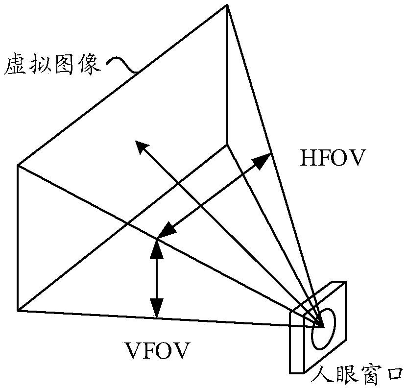
[0055] Field of view (FOV): It can also be called field of view or field of view, which refers to the angle at which an object is seen through the lens, which can be obtained by measuring the angle of the object in the horizontal direction and the angle in the vertical direction. The size of the FOV determines the field of view of the optical instrument. Usually FOV is measured in angles.

[0056] Eyebox: The space in which a lens or visual display forms an effective visible image, and the size of the exit pupil is related to the distance from the eyepiece to the eye. eyebox refers to the extent to which the eyeballs can move without affecting the display effect. Larger eyebox users are les...


PUM


Abstract

The invention provides a waveguide assembly and a near-to-eye display device using the waveguide assembly. The waveguide assembly comprises a first exit pupil extension waveguide structure 710 and a second exit pupil extension waveguide structure 720, wherein the contact face 730 of the first exit pupil extension waveguide structure 710 and the second exit pupil extension waveguide structure 720 is tilted with respect tothe xz plane of a coordinate system xyz;the first exit pupil extension waveguide structure 710 comprises a plurality of first optical thin film layers, one ends of the first optical thin film layers all extend to the contact surface 730, so that the lengths of the first optical thin film layers sequentially increase along a light beam in the transmission direction of the first exit pupil extension waveguide structure 710, and thus the light beam can be effectively reflected through the first optical thin film layers into the second exit pupil extension waveguide structure so as to reduce stray light in the waveguide assembly.

Description

technical field [0001] The present application relates to the field of optics, and more particularly, to waveguide components and near-eye display devices in the field of optics. Background technique [0002] Retinal scan display (RSD or virtual retina display, VRD) technology refers to a new display technology that directly projects images to the user's retina by means of beam scanning. This display technology uses a high-speed scanning device to control the light beam generated by the light source, so that the light beam is modulated sequentially according to a certain path according to the image information. The optical projection system projects the outgoing light of the scanning device to the human eye and directly forms an image on the retina. Since this display technology does not require a physical display surface, and only generates and modulates the required pixels, it is very suitable for near-eye displays such as augmented reality (AR), mixed reality (mixed reali...

Claims


Application Information

Patent Timeline
Patent Type & Authority Applications(China)
IPC IPC(8): G02B27/01
CPCG02B27/0172
Inventor 王玘周海峰谢振霖
Owner HUAWEI TECH CO LTD
Why Eureka
Try Eureka