Integrated mud stirring machine for operating paddy field

A slurry mixer and integrated technology, applied in the field of integrated operation paddy field mixer, can solve problems such as shortening the service life of the equipment, uneven bearing load, bearing wear, etc., to avoid the phenomenon of water digging, ensure efficiency, and reduce mixing The effect of mud resistance

Pending Publication Date: 2019-07-30
北京德邦大为科技股份有限公司
View PDF0 Cites 0 Cited by
  • Summary
  • Abstract
  • Description
  • Claims
  • Application Information

AI Technical Summary

Problems solved by technology

[0004] In addition, the conventional operation equipment is connected to the rear of the tractor by manually adjusting the relative position of the tractor and the operation equipment, and then pin connection is carried out through the through pin, which is difficult to connect
[0005] The driving principle of the crushing roller or pulping roller of traditional operating equipment is driven by one side, and the other side is only connected by bearings. For operating equipment with a relatively wide width, or a crushing roller or a pulping roller with a large workload, It is easy to cause uneven load bearing on both sides, and it is easy to cause serious wear of the bearing on one side, shortening the service life of the equipment; in modern agricultural production, the larger the width of the operating equipment, the higher the efficiency of large-area operations

Method used


Image

  • Integrated mud stirring machine for operating paddy field
  • Integrated mud stirring machine for operating paddy field
  • Integrated mud stirring machine for operating paddy field

Examples


Embodiment 1

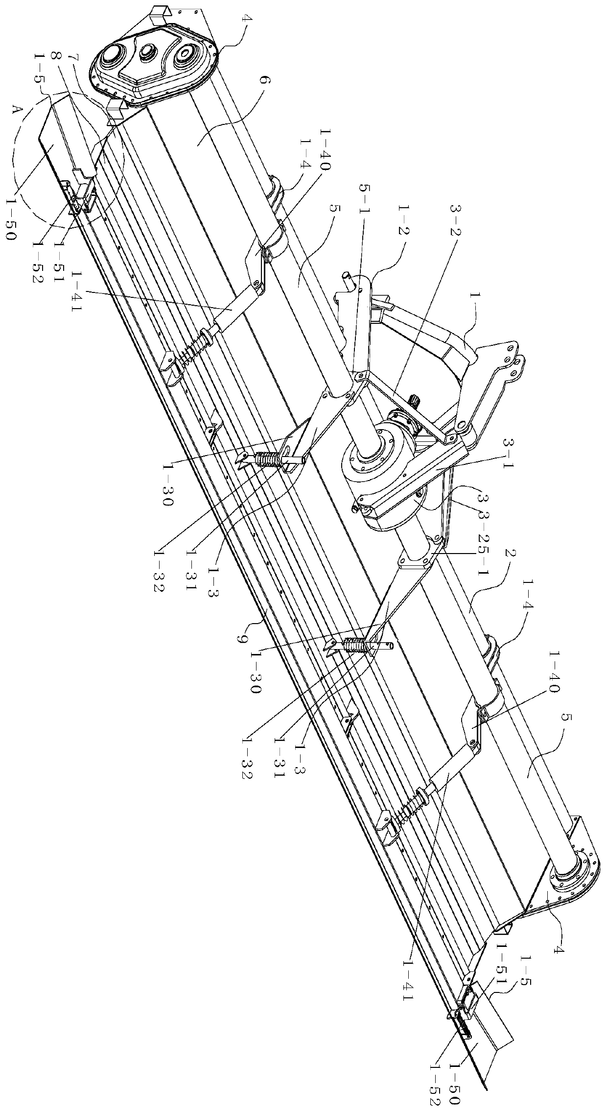
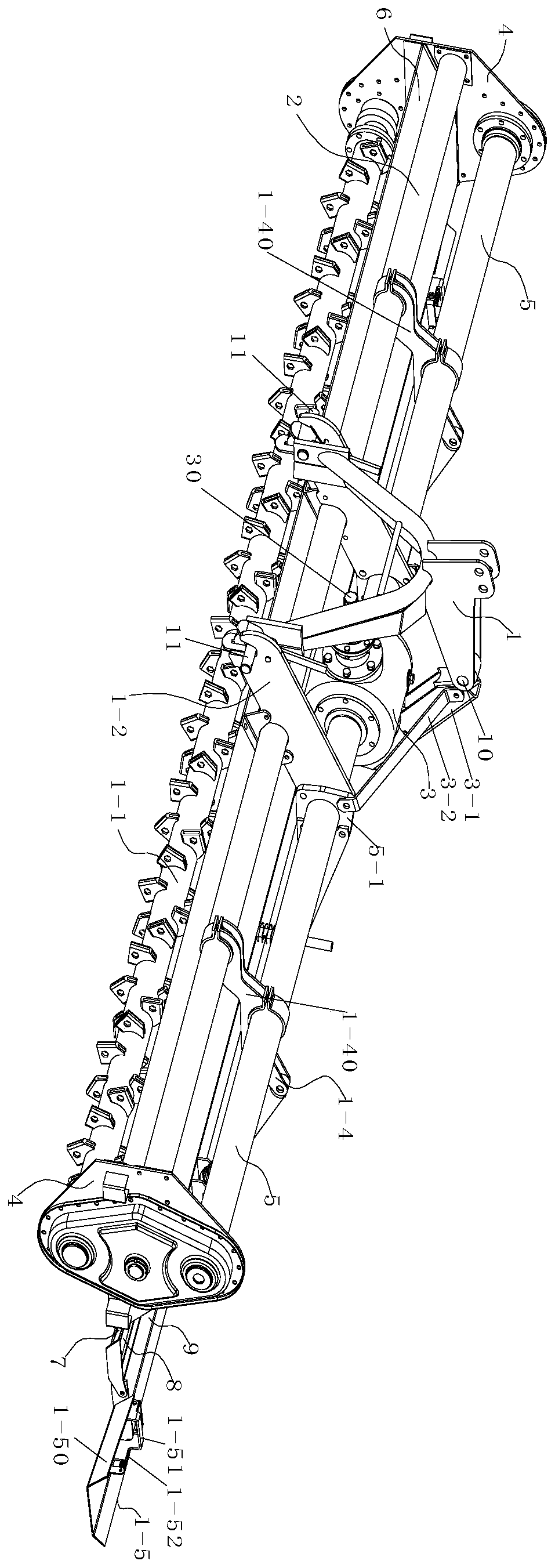
[0065] In this integrated operation paddy field mixer, the upper end of the three-point suspension frame 1 is connected with the diagonal stay rod 3-1 through the hinge joint 10, and the diagonal stay rod 3-1 is tightly connected with the gear box 3, and the diagonal stay rod 3-1 is two A stabilizer bar 3-2 is arranged symmetrically on the side, and one end of the stabilizer bar 3-2 is tightly connected to the side wall of the diagonal stay rod 3-1, and the other end is firmly connected to the connecting plate 5-1, and the lower end of the three-point suspension frame 1 is symmetrical Bearing pin 11 is provided, and pin shaft 11 is provided with through through hole, and the coupling tube of tractor rear end is worn on pin shaft 11, then passes through coupling tube and through hole through locking pin, then starts tractor, makes When the tractor moves backwards, the coupling cylinder moves backwards with the pin shaft 11, because the suspension lock 12 is composed of a suspens...

Embodiment 2

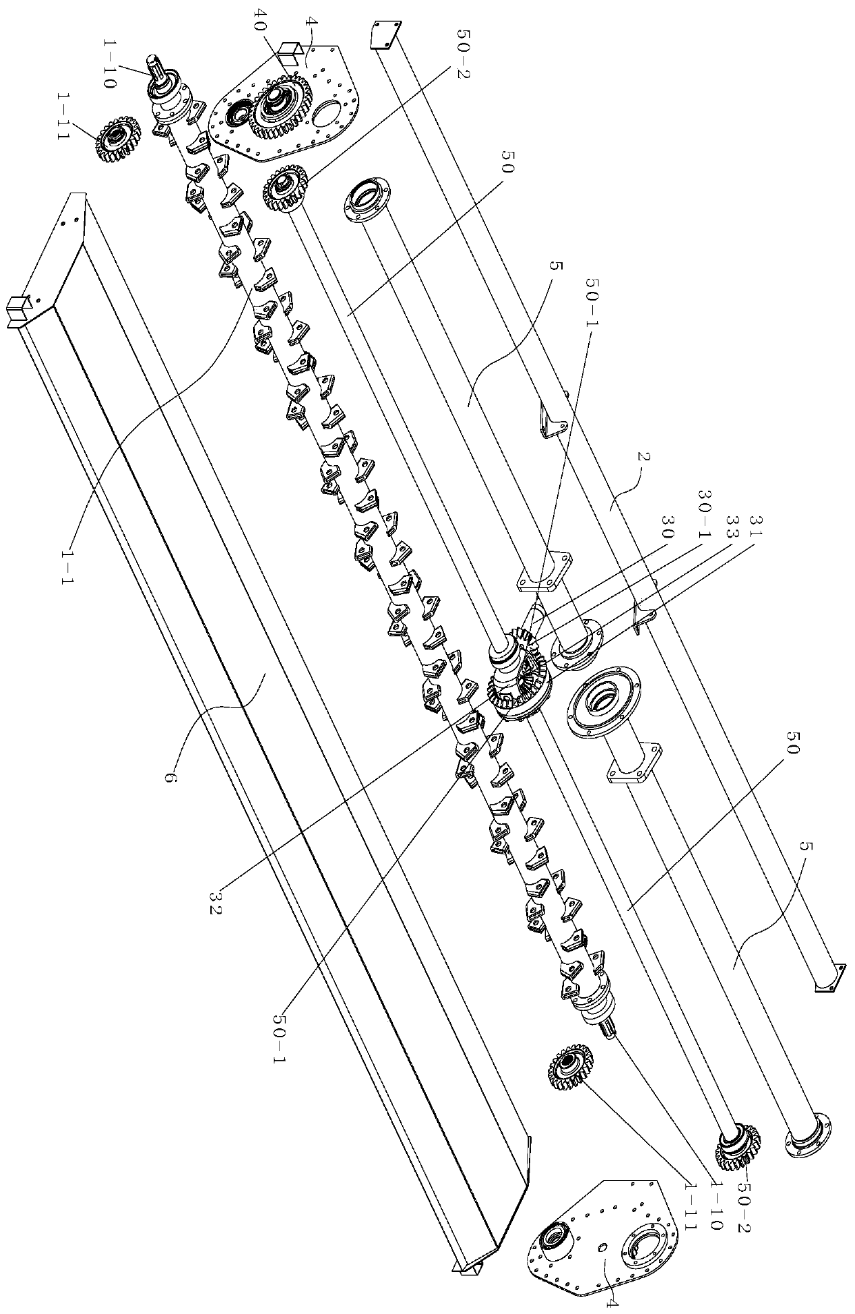
[0067] In this integrated operation paddy field mixer, the two ends of the mixing roller 1-1 are respectively provided with spline shafts 1-10, and the spline shafts 1-10 are rotatably connected to the lower end of the side panel 4 through bearings. The key shaft 1-10 is provided with a spur gear 2 1-11, the horizontal shaft sleeve 5 is provided with a rotating shaft 2 50, and one end of the rotating shaft 50 is provided with a spur gear 1 50-2, and the center of the side panel 4 is rotated. There is a reversing gear 40, and the spur gear 1 50-2 and the spur gear 2 1-11 are respectively externally meshed with the reversing gear 40. The front end of the gearbox 3 is provided with an input shaft 30, and the end of the input shaft 30 is located at the gear Bevel gear 1 30-1 is provided inside the box 3, and bevel gear 2 31 and planetary carrier 32 are arranged in the gear box 3, and bevel gear 1 30-1 meshes with bevel gear 2 31, and the center rotation of the planetary carrier 32 ...

Embodiment 3

[0069] In this integrated operation paddy field mixer, the platen mechanism 1-3 is composed of a limit plate 1-30, a support rod 1-31 and a compression spring 1-32, and the front end of the limit plate 1-30 is connected to the connecting plate 5-1 is tightly connected, the upper end of the support rod 1-31 passes through the limit plate 1-30, and the lower end is hinged with the hinge seat 1-80, and the compression spring 1-32 is sleeved on the support rod 1-31, The upper end of compression spring one 1-32 is in contact with the lower side of the limit plate 1-30, the lower end of compression spring one 1-32 is in contact with the pin passing through the support rod 1-31, and the limit plate 1-30 is installed horizontally so that the support The rod 1-31 is in a vertical state, under the action of the elastic restoring force of the stage clip 1-32, the active force acting on the support rod 1-31 is vertically downward, acting on the first pressing plate 8, so that The first pl...


PUM


Abstract

The invention discloses an integrated mud stirring machine for operating a paddy field. The integrated mud stirring machine comprises a three-point suspension bracket, a transverse stabilizer bar, a gear box, a side enclosing plate, transverse shaft sleeves, a mud baffle, a rubber plate, a first pressing plate, a second pressing plate, a mud stirring roller, a suspension lock, a pressing plate mechanism, a pressing mechanism and a trowelling mechanism, wherein the transverse stabilizer bar is connected with the side enclosing plate; the transverse shaft sleeves are symmetrically arranged on the two sides of the gear box; one end of each transverse shaft sleeve is connected with the gear box, and the other end of the each transverse shaft sleeve is connected with the side enclosing plate; the mud baffle is connected with the side enclosing plate; one end of the rubber plate is riveted with the mud baffle, and the other end of the rubber plate is riveted with the first pressing plate; the first pressing plate is articulated with the second pressing plate; the two ends of the mud stirring roller are rotatably connected with the side enclosing plate; a connecting plate is arranged on the transverse shaft sleeves; the suspension lock is connected with the connecting plate; the pressing plate mechanism is connected with the connecting plate; the lower end of the pressing plate mechanism is connected with the first pressing plate; one end of the pressing mechanism is fixedly connected with the transverse stabilizer bar and the transverse shaft sleeves and articulated with the upper end of the second pressing plate; the trowelling mechanism is tightly articulated with two ends of the second pressing plate. Therefore, an integrated mud stirring operation is achieved.

Description

technical field [0001] The invention belongs to the technical field of agricultural machinery, in particular, the invention relates to an integrated operation paddy field mixer. Background technique [0002] With the technical development of mechanical automation equipment, agricultural automation has gradually spread to existing agricultural operations. In the traditional small-scale peasant economy era, the method of using manual labor and livestock for operations has gradually been replaced. [0003] Most of the current paddy fields are planted by rice transplanters or directly sowing seeds. No matter what planting method is used, the roots of the seedlings or sowing seeds need to be fully in contact with the mud and wrapped in mud. This is important for paddy field mixers. The performance requirements are higher than those of traditional operating equipment. Before planting, it is necessary to ensure the thickness of the mud layer on the surface of the paddy field, and t...

Claims


Application Information

Patent Timeline
IPC IPC(8): A01B49/02A01B33/10A01B33/08A01B35/14A01B35/26A01B35/20A01B59/06
CPCA01B49/022A01B33/103A01B33/082A01B33/08A01B35/14A01B35/26A01B35/20A01B59/066
Inventor 刘汉武刘繁华孙宏宇刘丹李志兴
Owner 北京德邦大为科技股份有限公司
Why Eureka
Try Eureka