Deep sea mounting releasing mechanism

A release mechanism, deep-sea technology, applied in underwater operation equipment, transportation and packaging, ships, etc., can solve the problem of low stability of the mount release mechanism, achieve good application prospects, convenient release, simple and firm structure

Active Publication Date: 2019-07-30
ZHONGBEI UNIV
View PDF5 Cites 2 Cited by
  • Summary
  • Abstract
  • Description
  • Claims
  • Application Information

AI Technical Summary

Problems solved by technology

[0004] In view of the above problems, the purpose of the present invention is to solve the technical problem of the low stability of the traditional mount release mechanism in the deep sea environment

Method used


Image

  • Deep sea mounting releasing mechanism
  • Deep sea mounting releasing mechanism
  • Deep sea mounting releasing mechanism

Examples


Embodiment 1

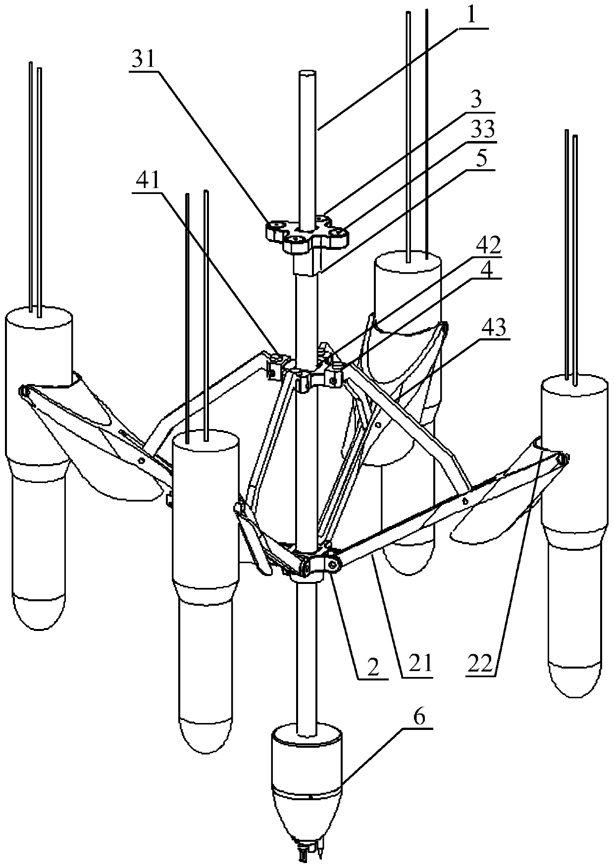
[0029] In order to solve the technical problem of low stability of the traditional mount release mechanism in the deep sea environment, this embodiment proposes a deep sea mount release mechanism, which uses the attraction between the electromagnet 33 and the iron block 41 to pull the mechanical structure to complete the deep sea release ,like figure 1 As shown, it includes: a power supply, a center rod 1 and a bracket seat 2. The center rod 1 is provided with a magnet seat 3, a tie rod seat 4 and a bracket seat 2 from top to bottom, and the magnet seat 3 and the bracket seat 2 are fixed on the center rod 1. The rod seat 4 is sleeved on the central rod 1, such as Figure 9 As shown, the magnet base 3 is provided with not less than one first through hole 31, and an electromagnet 33 is fixed in the first through hole 31, and the pull rod seat 4 is connected with not less than one pull rod 43 through a shaft. 4 The upper surface is fixed with an iron block 41 that matches the el...

Embodiment 2

[0047] Based on the deep sea mount release mechanism disclosed in Embodiment 1, this embodiment discloses the operation method of the deep sea mount release mechanism, specifically as follows:

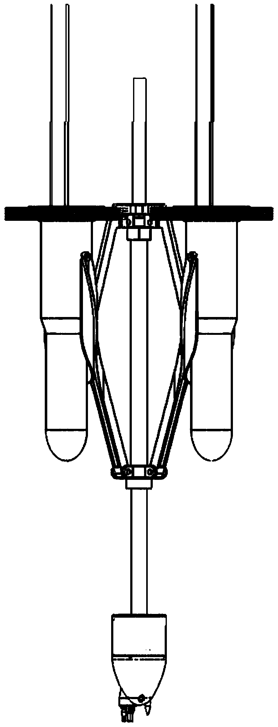
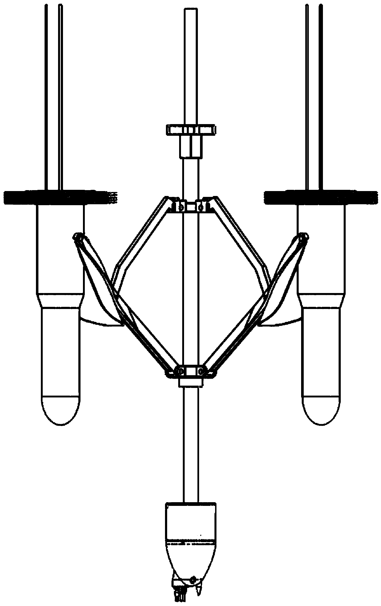
[0048] Pull the rod seat 4 to the lower surface of the magnet seat 3, so that the electromagnet 33 and the iron block 41 are firmly sucked, and then the object to be released is fixed in the groove of the arc-shaped slot 22 to complete the mounting work, and then the The deep-sea mounting release mechanism of this embodiment is slowly submerged in seawater until the preset position. At this time, the pull rod 43 and the support 21 of the deep-sea mounting release mechanism of this embodiment are in a contracted state, that is, when the clamp between the pull rod 43 and the support 21 When the angle is much larger than 90°, such as figure 2 As shown, the object to be released is in a mounted state. When the pull rod 43 and the bracket 21 are in a tightened state, there is an angle of i...


PUM


Abstract

The invention relates to the technical field of release devices, in particular to a deep sea mounting releasing mechanism. The deep sea mounting releasing mechanism comprises a power supply, a centralrod and a bracket seat, wherein the central rod is provided with a magnet seat, a pull rod seat and a bracket seat from top to bottom; an electromagnet is fixed in a first through hole; at least onepull rod is connected to the pull rod seat through a shaft; at least one iron block is fixed to the upper surface of the pull rod seat; at least one bracket is connected to the bracket seat through ashaft; one ends of the pull rods are connected to a non-end point position of a bracket through the shaft; and an arc-shaped clamping groove is formed in the end, away from the central rod, of the bracket. The mechanical movement among the pull rods, the bracket and the arc-shaped clamping groove is controlled by utilizing the attraction effect of the electromagnet and the iron blocks so as to realize the mounting and accurate releasing of the to-be-released substance in the deep sea; the structure is simple and firm, the operation is convenient, the problem of low stability of a traditional release mechanism in the deep sea environment can be solved, and the deep sea mounting releasing mechanism has good practical value.

Description

technical field [0001] The invention relates to the field of release devices, in particular to a deep-sea mounted release mechanism. Background technique [0002] Marine resources have always been closely watched by people. The exploration and detection of the marine environment is the technical basis for the development of modern marine technology. In the exploration of the deep-sea environment, it is often necessary to mount and release various deep-sea detectors at different depths. At present, ocean turbulence is an important research field of ocean physics. The existence of turbulence problems has prevented the research and development of many other disciplines. In the study of ocean turbulence, an effective and reliable release device is essential. important equipment. [0003] In addition to the release form of the acoustic release device, the locking pin is usually driven by a motor to expand and contract or rotate, and there are also separation and release methods ...

Claims


Application Information

Patent Timeline
Patent Type & Authority Applications(China)
IPC IPC(8): B63C11/52
CPCB63C11/52
Inventor 薛晨阳张志东梁霄年夫顺
Owner ZHONGBEI UNIV
Why Eureka
Try Eureka