Positioning coupler

A coupling and coaxial technology, applied in the direction of couplings, elastic couplings, mechanical equipment, etc., can solve the problem of affecting the stability and service life of coupling equipment, and cannot effectively meet the needs of large-load driving operations and stability. And the weak connection structure strength and other problems, to achieve good positioning and braking ability, improve power transmission ability and stability, improve the effect of structural strength and bearing capacity

Inactive Publication Date: 2019-07-30
江苏泰克曼传动设备有限公司
0 Cites 1 Cited by

AI-Extracted Technical Summary

Problems solved by technology

[0002] Elastic coupling is a very common coupling equipment in the current coupling equipment. It is used in a huge amount in the connection of mechanical equipment, reducers and motors, and mechanical equipment transmission shafts. However, it is found in use that the current elasticity During the operation of the coupling, on the one hand, the stability of the connection relationship between the connecting flanges on both sides of the coupling and the strength of the connection structure are relatively weak, which cannot effectively meet the needs of large-load driving operations, and cause problems during the operation of the coupling. The axial movement, radial runout ...

Method used

In the operation of the present invention, the shaft rod workpiece is connected and positioned by the left flange and the right flange, and the driving force is transmitted between the left flange and the right flange by connecting the claws, and the left flange and the right flange The blue and connecting claws jointly improve the structural strength and impact resistance of the elastic coupling; at the same time, the elastic matrix and the elastic lining jointly improve the elastic deformation capacity of the elastic coupling of the present invention, so as to effectively eliminate the axial deformation of the coupling during operation. The movement and radial runout force can improve the stability of the coupling operation. Finally, during the operation p...

Abstract

The invention relates to a positioning coupler. The positioning coupler comprises a left flange, a right flange, a brake wheel, a connecting clamping jaw and an elastic base body, wherein the left flange and the right flange are coaxially distributed, the left flange is connected with the right flange through the connecting clamping jaw, the outer side surface of the elastic base body abuts against the inner side surface of the connecting clamping jaw, and the left end surface and the right end surface of the connecting clamping jaw are connected with the left flange and the right flange to abut against the bottom of the clamping jaw, the brake wheel wraps outside the left flange, and the rear end surface of the connecting clamping jaw connected with the left flange is connected with the rear end surface of the brake wheel through a positioning bolt. According to the positioning coupler, on one hand, the structure strength and bearing capability can be effectively improved, and the power transmission capacity and stability are greatly improved; and on the other hand, the purpose of synchronous braking and speed regulation operation of the coupler and a shaft rod workpiece can be achieved, and the damage condition of the coupler structure caused by inertia during the running process of the coupler and the shaft rod workpiece can be effectively eliminated.

Application Domain

Yielding coupling

Technology Topic

EngineeringPower transmission +3

Image

  • Positioning coupler

Examples

  • Experimental program(1)

Example Embodiment

[0014] In order to make the technical means, creative features, objectives and effects of the present invention easy to understand, the present invention will be further explained below in conjunction with specific embodiments.
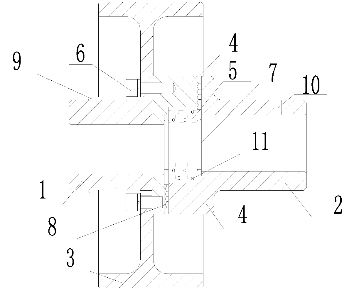
[0015] Such as figure 1 The described positioning coupling includes a left flange 1, a right flange 2, a brake wheel 3, a connecting jaw 4, and an elastic base 5, wherein the left flange 1 and the right flange 2 are coaxially distributed, and The front ends of the left flange 1 and the right flange 2 are all connected to a connecting jaw 4 and distributed coaxially with the connecting jaw 4, and the left flange 1 and the right flange 2 are connected to each other through the connecting jaw 4, which is elastic The base body 5 is a hollow tubular structure coaxially distributed with the left flange 1 and the right flange 2, and the outer surface of the elastic base body 5 abuts against the inner surface of the connecting jaw 4, and the left and right end faces respectively align with the left flange 1 and the right flange. The bottom of the connecting claw 4 at the flange 2 abuts, the brake wheel 3 is wrapped around the left flange 1 and distributed coaxially with the left flange 1, and the spokes of the brake wheel 3 are connected to the rear end of the connecting claw 4 of the left flange 1. They are connected to each other by positioning bolts 6. The outer diameter of the brake wheel 3 is 1.3 to 3 times the diameter of the connecting jaw 4, and the distance between the rear end of the brake wheel 3 and the rear end of the left flange 1 is 1/the length of the left flange 1. 4-1/3, the front end of the brake wheel 3 and the rear end of the connecting jaw 4 connected to the right flange 2 are evenly distributed. The left and right end faces of the elastic base body 5 are at least A disc spring 7, and the disc spring 7 is coaxially distributed with the left flange 1 and the right flange 2, and the contact surfaces of the connecting jaws 4 connected by the left flange 1 and the right flange 2 Set the elastic liner 8.
[0016] At the same time, the brake wheel 3 and the outer surface of the left flange 1 are slidably connected to each other through at least two sliding grooves 9, and the sliding grooves 9 are evenly distributed around the axis of the left flange 1 and parallel to the axis of the left flange 1. distributed.
[0017] In a further optimization, at least one positioning pin hole 10 is provided on the side surfaces of the left flange 1 and the right flange 2, and the positioning pin hole 10 axis is perpendicular to the axis of the left flange 1 and the right flange 2.
[0018] For further optimization, a number of deformation cavities 11 are evenly distributed in the elastic base 5, and the axis of the deformation cavity and the axis of the elastic base 5 form an angle of 0°-90°.
[0019] In the specific embodiment of the present invention, the left flange, right flange, brake wheel, connecting jaws, and elastic base constituting the present invention are first assembled, and then the assembled present invention is passed through the left flange and right flange. It is connected with the shaft workpiece to be connected, and at the same time the brake wheel and the external brake mechanism are connected to each other, thereby completing the assembly of the present invention.
[0020] In the operation of the present invention, the shaft workpiece is connected and positioned through the left flange and the right flange, and the driving force transmission between the left flange and the right flange is realized through the connecting jaws, and the left flange, the right flange, and the connection The jaws jointly improve the structural strength and impact resistance of the elastic coupling; at the same time, the elastic matrix and the elastic lining layer jointly improve the elastic deformation ability of the elastic coupling of the present invention, so as to effectively eliminate the axial movement and impact of the coupling during operation. The radial jump action exerts force to improve the stability of the coupling operation. Finally, during the operation, the braking force is directly applied to the braking wheel through the braking mechanism, and the elastic coupling of the present invention is assisted by the loading and positioning of the braking mechanism. At the same time, it is also possible to adjust the rotational speed of the elastic coupling of the present invention during operation, so that the rotational speed of the elastic coupling of the present invention is consistent with the rotational speed of the shaft workpiece, and prevents the elastic coupling of the present invention from being higher However, the situation of being damaged by large torque occurs, thereby improving the stability and reliability of the operation of the elastic coupling of the present invention.
[0021] The invention has simple structure, flexible and convenient use, and good versatility. On the one hand, it can effectively improve the structural strength and load-bearing capacity. While greatly improving the power transmission capacity and stability, it can effectively reduce the axial displacement generated in the power transmission process. The dynamic and radial jump actions forcefully improve the operation stability of the coupling equipment. On the other hand, it also has good positioning and braking capabilities, which can improve the coaxiality of the coupling operation, and also realize the coupling and The purpose of synchronous braking and speed regulation of the shaft workpiece is to effectively eliminate the damage to the coupling structure caused by the inertia of the coupling and the shaft workpiece during operation.
[0022] Those skilled in the industry should understand that the present invention is not limited by the foregoing embodiments. The foregoing embodiments and descriptions in the specification only illustrate the principles of the present invention. Without departing from the spirit and scope of the present invention, the present invention may have various changes and improvements. These changes and improvements fall within the scope of the claimed invention. The scope of protection claimed by the present invention is defined by the appended claims and their equivalents.

PUM

no PUM

Description & Claims & Application Information

We can also present the details of the Description, Claims and Application information to help users get a comprehensive understanding of the technical details of the patent, such as background art, summary of invention, brief description of drawings, description of embodiments, and other original content. On the other hand, users can also determine the specific scope of protection of the technology through the list of claims; as well as understand the changes in the life cycle of the technology with the presentation of the patent timeline. Login to view more.

Similar technology patents

Photoelectric sensor for position of sun

InactiveCN101650173AEffective tracking range expandedSimple structure
Owner:WUHAN UNIV OF TECH

Magnetic cooling apparatus and control method thereof

ActiveUS20130180263A1simple structure
Owner:SAMSUNG ELECTRONICS CO LTD

Dual-Drivetrain of Power-Assist Vehicle

InactiveUS20100181130A1enhance uphill momentumsimple structure
Owner:CHOU WEN CHENG

Classification and recommendation of technical efficacy words

  • Simple structure
  • easy to use

Laser assisted total joint arthroplasty

InactiveUS20090234360A1easy to use
Owner:ALEXANDER VLADIMIR

Enclosure for a portable hemodialysis system

ActiveUS20090114582A1easy to use
Owner:DEKA PROD LLP
Why Eureka
Try Eureka