In-situ sample rod for transmission electron microscopy

An electron microscope and sample rod technology, applied in circuits, discharge tubes, electrical components, etc., can solve problems such as inapplicability, inability to achieve accurate temperature control in low temperature areas, and inability to achieve accurate temperature control in full temperature areas, and achieve a wide range of applications. Effect

Pending Publication Date: 2019-07-30
关一 +1
View PDF0 Cites 2 Cited by
  • Summary
  • Abstract
  • Description
  • Claims
  • Application Information

AI Technical Summary

Problems solved by technology

[0008] The first purpose of the present invention is to solve the technical problem that the in-situ sample rod used in the transmission electron microscope cannot realize precise temperature control in the low temperature zone;
[0009] The second purpose of the present invention is to solve the technical problem that the in-situ sample rod used in the transmission electron microscope cannot realize accurate temperature control in the whole temperature zone;
[0010] The third purpose of the present invention is: to solve the technical problem that the in-situ sample rod for transmission electron microscope can only be used for solid samples but not for gas and liquid samples at least when testing in low temperature regions

Method used


Image

  • In-situ sample rod for transmission electron microscopy
  • In-situ sample rod for transmission electron microscopy
  • In-situ sample rod for transmission electron microscopy

Examples


Embodiment Construction

[0034] In order to better explain the present invention and facilitate understanding, the present invention will be described in detail below through specific embodiments in conjunction with the accompanying drawings.

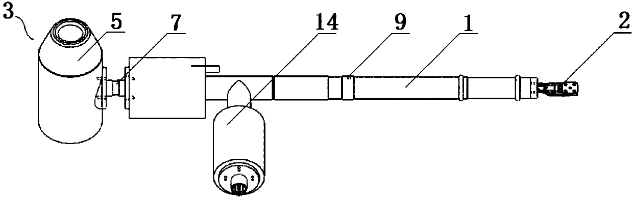
[0035] refer to figure 1 , the present embodiment provides an in-situ sample rod for a transmission electron microscope (hereinafter referred to as the sample rod). The sample rod includes a sample rod shaft 1, a sealed test chamber 2, a passive refrigerator 3, an active refrigerator 4, a temperature detector and a temperature controller.

[0036] Wherein, the sample rod shaft 1 is a revolving body with a circular cross section, which itself is composed of a plurality of rod segments connected in series. Positioning pins 9 are provided on the outer peripheral surface of the sample rod shaft 1, so that the sample rod can be positioned by the positioning pins 9 after being inserted into the transmission electron microscope so that it can rotate ±30° around its o...


PUM


Abstract

The invention relates to the technical field of material analysis and test, in particular to the field of in-situ measurement and research of a transmission electron microscopy part and a low-dimensional material. By an in-situ sample rod for a transmission electron microscopy, the technical problem the accurate temperature control of a low-temperature region cannot be achieved is solved, and thein-situ sample rod for the transmission electron microscopy is provided. The sample rod comprises a sample rod body, a sealing test cavity, a passive refrigerator, an active refrigerator, a temperature measurement device and a temperature controller, wherein the sealing test cavity is arranged in front of the sample rod body, the passive refrigerator is used for performing passive refrigerating onthe sealing test cavity, the active refrigerator is used for performing active refrigerating on the sealing test cavity, the temperature measurement device is used for detecting a temperature in thesealing test cavity, and the temperature controller is used for controlling the active refrigerator to achieve active refrigerating according to a measurement value of the temperature measurement device. The passive refrigerator is used as primary refrigerating, the active refrigerator is used as secondary refrigerating, and the sample rod can be used for achieving accurate temperature control ofthe low-temperature region.

Description

technical field [0001] The invention relates to the technical field of material analysis and testing, in particular to the research field of transmission electron microscope accessories and in-situ measurement of low-dimensional materials. Background technique [0002] The structural changes of materials at the sub-nanometer or atomic scale caused by the coupling of the surrounding environment and multi-physics external fields are the root of their macroscopic properties, and whether the microstructure of materials under the action of the environment and external fields can be observed at the sub-nanometer or atomic scale The evolution of structure or chemical composition becomes the key to understanding the properties of materials. The in-situ and real-time high-resolution characterization technology of nanoscale structures and properties under the action of the environment and external fields directly determines our cognition ability for materials, and is the key to realiz...

Claims


Application Information

Patent Timeline
Patent Type & Authority Applications(China)
IPC IPC(8): H01J37/20H01J37/26
CPCH01J37/20H01J37/261
Inventor 关一王忠良
Owner 关一
Why Eureka
Try Eureka