
Automatic feeding and discharging device

An automatic loading and unloading and distributing device technology, which is applied in the direction of grinding feed movement, grinding workpiece support, grinding machine tool parts, etc., can solve problems such as low labor efficiency, affecting positioning accuracy, and lagging loading and unloading mechanisms. Achieve the effect of high-quality processed products, solve bumps and accurate loading and unloading

Inactive Publication Date: 2019-08-02
常州市邹区蔬菜产业发展有限公司
View PDF0 Cites 0 Cited by
  • Summary
  • Abstract
  • Description
  • Claims
  • Application Information

AI Technical Summary

Problems solved by technology

At present, the loading and unloading mechanism of domestic bearing ring grinding processing equipment is backward, and the loading and unloading machinery for small products has bumps and damages, which affects product quality.
In addition, the noise is also large
The main reason is that the loading and unloading depends on the weight of the workpiece to roll to the position of the machining center on the inclined surface, which has a large impact on the positioning support point and affects the positioning accuracy.
For medium and large size bearing rings, in order to overcome the above problems, manual loading and unloading is used. The machine tool cannot realize automatic processing, the labor efficiency is low, and the labor intensity of the workers is high. This problem has not been solved by domestic professional manufacturers.

Method used


Image

  • Automatic feeding and discharging device
  • Automatic feeding and discharging device
  • Automatic feeding and discharging device

Examples


Embodiment Construction

[0009] The present invention will be described in further detail below in conjunction with the accompanying drawings and embodiments. It should be understood that the specific embodiments described here are only used to explain the present invention, not to limit the present invention.

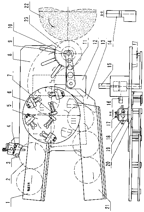
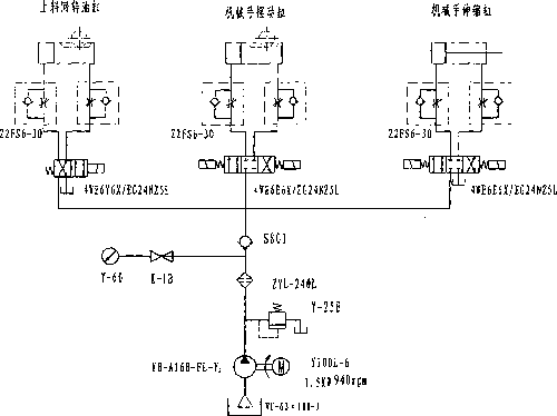
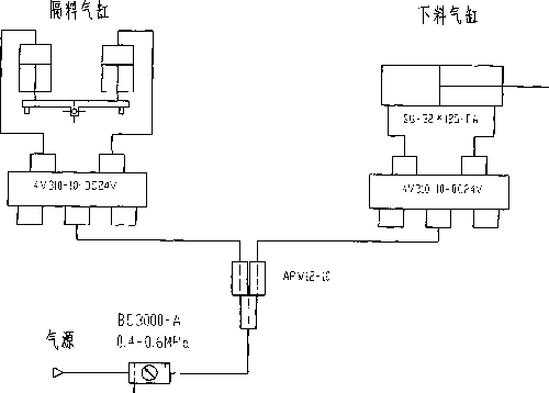
[0010] Such as Figure 1-Figure 3 As shown, the present invention schematically shows an automatic loading and unloading device.

[0011] The invention discloses an automatic loading and unloading device. figure 1 , figure 2 with image 3 Among them, the feeding channel 1 is connected with the panel 8, the workpiece 2 is located in the feeding channel 1, the panel 8 is connected with the distribution device 3, and the distribution device 3 has a distribution cylinder 4; the panel 8 is connected with the oil cylinder to fix Block 19, the material protection plate 6 and the support block 7 are installed on the rotary disk 5, the adjustment plate 9 is connected to the panel 8, the clamping h...


PUM


Abstract

The invention provides an automatic feeding and discharging device. The automatic feeding and discharging device comprises a feeding channel, a workpiece, a material distributing device, a material distributing air cylinder, a rotary disc, a material protecting plate, a material supporting block, a panel, an adjusting plate, a mechanical clamping jaw, a mechanical clamping jaw telescopic rotary fixing frame, a sliding plate, a disc rotary oil cylinder, a mechanical clamping jaw telescopic oil cylinder, a mechanical clamping jaw rotary oil cylinder, a rack, a gear, an oil cylinder fixing block,a rotating shaft, a discharging channel, a grinding wheel and a workpiece grinding central position which are connected, wherein the feeding channel is connected with the panel, the workpiece is positioned in the feeding channel, the material distributing device is connected to the panel, the material distributing air cylinder is arranged in the material distributing device, the oil cylinder fixing block is connected to the panel, the material protecting plate and the material supporting block are installed on the rotary disc, and the adjusting plate is connected to the panel.

Description

technical field [0001] The invention relates to the technical field of processing machinery, in particular to the field of automatic loading and unloading devices. Background technique [0002] With the rapid development of my country's machinery industry, new requirements are put forward for the bearing equipment industry. Bearing grinding equipment must be upscale, which requires bearing grinding equipment to process products with good quality, high efficiency, stable equipment performance, and advanced technology. At present, the loading and unloading mechanism of domestic bearing ring grinding equipment is backward, and the loading and unloading machinery for small products has bumps and damages, which affects product quality. In addition, the noise is also large. The main reason is that loading and unloading rely on the weight of the workpiece to roll to the position of the machining center on the inclined surface, which has a large impact on the positioning support p...

Claims


Application Information

Patent Timeline
Patent Type & Authority Applications(China)
IPC IPC(8): B24B41/00B24B41/06
CPCB24B41/005B24B41/06
Inventor 钱丽婷
Owner 常州市邹区蔬菜产业发展有限公司
Learn More