Multifunctional perforating device used for wall surfaces
A punching device and multi-functional technology, applied in stone processing tools, working accessories, manufacturing tools, etc., can solve the problems of poor accuracy and dust splashing, so as to reduce dust pollution, prevent dust splashing, and improve accuracy Effect
- Summary
- Abstract
- Description
- Claims
- Application Information
AI Technical Summary
Problems solved by technology
Method used
Image

Examples
Embodiment 1
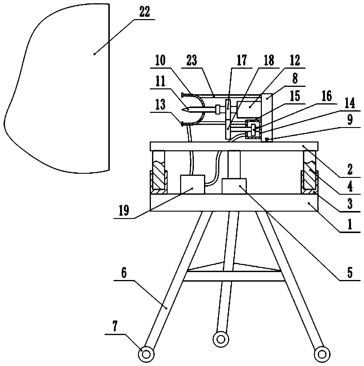
[0025] Embodiment one is basically as attached figure 1 , figure 2 Shown:
[0026] The multifunctional punching device for the wall, including the base 1 and the support base 2, the support column is connected between the base 1 and the support base 2, the support column is composed of the outer rod 3 and the inner rod 4 slidingly socketed, and the lower end of the outer rod 3 is welded On the base 1, the upper end of the inner rod 4 is welded on the support base 2, and the base 1 is fixedly connected with a hydraulic cylinder 5 by bolts, and the output shaft of the hydraulic cylinder 5 is fixedly connected with the support base 2. The outer bar 3 is hinged with a positioning bar, and the inner bar 4 is provided with a plurality of positioning grooves for the insertion of the positioning bars. Inserting the positioning bars into the positioning grooves can limit the sliding between the inner bar 4 and the outer bar 3 . Bolts on the base 1 are connected with a support frame ...
Embodiment 2
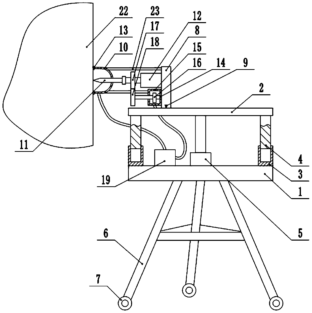
[0031] Embodiment two is basically as attached image 3 Shown:
[0032] In this embodiment, an air cylinder 20 is added on the basis of the first embodiment, that is, the cylinder 20 is connected with bolts on the support base 2 , and the output shaft of the air cylinder 20 is welded to the vertical plate 8 . When the vertical plate 8 is moved horizontally, it is driven by the cylinder 20 without manual operation, which can reduce the labor force and improve the efficiency.
Embodiment 3
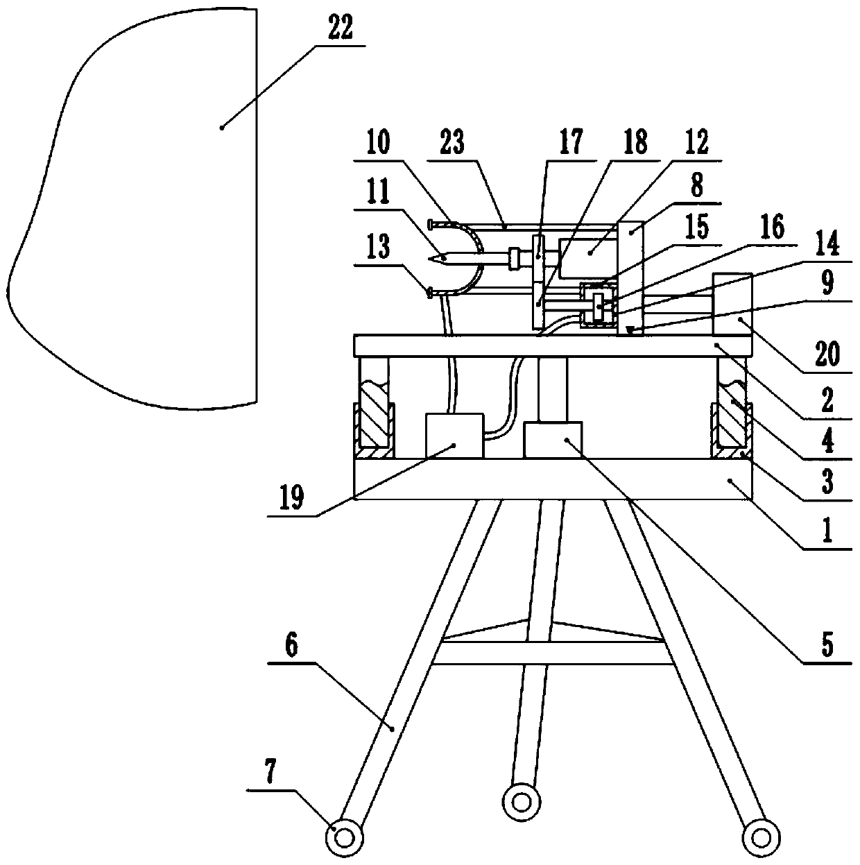
[0033] Embodiment three is basically as attached Figure 4 Shown:
[0034] In this embodiment, a controller 21 is added on the basis of Embodiment 2, that is, a controller 21 is connected with bolts on the base 1. In this embodiment, a PLC controller 21 whose model is UN2003-0808MR is selected. The input port of the controller 21 is connected with a jog switch for starting the hydraulic cylinder 5, a permanent switch for starting the cylinder 20, a touch switch for starting the motor 12, and a brake switch for closing the cylinder 20 and the motor 12 , the touch switch is installed on the side of the buffer block 13 in contact with the wall 22, and the output port of the controller 21 is electrically connected with the motor 12, the hydraulic cylinder 5 and the air cylinder 20.
[0035]When drilling, start the jog switch manually, so that the jog switch starts the hydraulic cylinder 5, the hydraulic cylinder 5 will drive the support base 2 to lift, and the support base 2 will...
PUM
 Abstract
Description
Claims
Application Information
 - R&D
- Intellectual Property
- Life Sciences
- Materials
- Tech Scout
- Unparalleled Data Quality
- Higher Quality Content
- 60% Fewer Hallucinations
Browse by: Latest US Patents, China's latest patents, Technical Efficacy Thesaurus, Application Domain, Technology Topic, Popular Technical Reports.
© 2025 PatSnap. All rights reserved.Legal|Privacy policy|Modern Slavery Act Transparency Statement|Sitemap|About US| Contact US: help@patsnap.com