Dirt discharge structure on tooth rake type bar screen machine

A technology of decontamination machine and grille, which is applied in the fields of water/sludge/sewage treatment, water/sewage treatment, chemical instruments and methods, etc. It can solve the problem that if there is sewage, floating and suspended matter need to be reprocessed through other equipment. In addition to sewage treatment, sewage will flow to the grille decontamination machine and other problems to achieve the effect of improving efficiency

Active Publication Date: 2019-08-02
温岭市山市金德利电器配件有限公司
View PDF4 Cites 0 Cited by
  • Summary
  • Abstract
  • Description
  • Claims
  • Application Information

AI Technical Summary

Problems solved by technology

At present, the commonly used sewage physical treatment methods are divided into sieve retention method, gravity separation method and centrifugal separation method, and the sieve retention method is mainly grille and screen mesh. Coarse floating and suspended solids ensure the normal operation of sewage treatment facilities. The grille decontamination machine uses a rotary rake to lift the floating and suspended solids from the grille to the upper end of the decontamination machine for dumping, and then transports them through the conveyor chain belt. Floating and suspended solids output; but it has disadvantages, there is sewage in the floating and suspended solids lifted by the tooth rake, and the floating and suspended solids need to be treated by other equipment for sewage removal, and the sewage will flow to the grille for removal Sewage machine

Method used


Image

  • Dirt discharge structure on tooth rake type bar screen machine
  • Dirt discharge structure on tooth rake type bar screen machine
  • Dirt discharge structure on tooth rake type bar screen machine

Examples


Embodiment

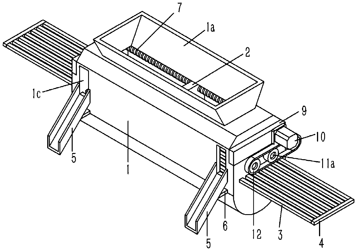
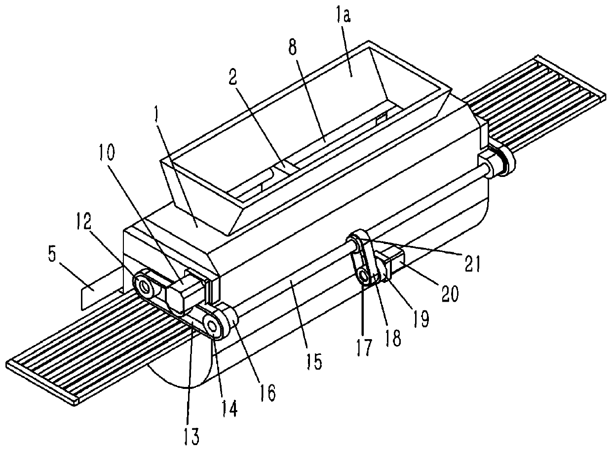
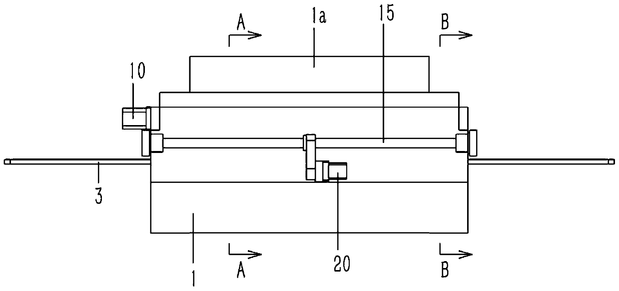
[0021] Example: see Figures 1 to 5 As described above, a dirt discharge structure on a rake-type grille decontamination machine includes a horizontal waste treatment box 1, the top of the waste treatment box 1 is formed with a conical feeding hopper 1a, and the bottom of the waste treatment box 1 The end is formed with a horizontal drainage groove 1b. The waste disposal box 1 is provided with a vertical extruding plate 2. The lower end of the extruding plate 2 is plugged and fixed with several horizontal retaining rods 3. The two ends of the retaining rod 3 The end passes through the left and right sides of the waste treatment box 1 and is fixedly connected to the limit rod 4; the front side of the upper end of the extrusion plate 2 is screwed with a horizontal lead screw 7, and the two ends of the lead screw 7 are inserted into the waste treatment The left and right side walls of the box 1 are against the limit baffle 9, and the limit baffle 9 is fixed on the left and right ...


PUM


Abstract

The invention discloses a dirt discharge structure on a tooth rake type bar screen machine. The dirt discharge structure comprises a horizontal waste material treatment tank, a conical feed hopper isformed in the top of the waste material treatment tank, a horizontal drainage channel is formed in the bottom of the waste material treatment tank, a vertical extruding plate is arranged in the wastematerial treatment tank, a plurality of horizontal stop levers are connected in an inserting way and fixed at the lower end of the extruding plate, the two ends of the stop lever penetrate through theleft side and the right side of the waste material treatment tank and are fixedly connected with a limiting rod, the front side of the upper end of the extruding plate is in screw connection with thea horizontal screw, the two ends of the screw are connected in an inserting way to the left side wall and the right side wall of the waste material treatment tank and are abutted against a limiting baffle plate, the limiting baffle plate is fixed on the left side wall and the right side wall of the waste material treatment tank, an extruding motor is fixedly connected to the limiting baffle plate, and a rotating shaft of the extruding motor is fixedly connected with the screw. The foreign matter intercepted by the tooth rake type bar screen machine is extruded to remove water, the foreign matter with the water removed is automatically outputted, and the sewage treatment efficiency is improved.

Description

technical field [0001] The invention relates to the technical field of sewage treatment devices, and more specifically relates to a sewage discharge structure on a rake-type grid decontamination machine. Background technique [0002] At present, both domestic sewage and industrial wastewater contain a large amount of floating matter and suspended matter, including inorganic and organic matter, and the content of suspended matter varies greatly; the removal objects of sewage physical treatment are suspended matter and floating matter. Physical treatment can be used alone or in combination with biological treatment or chemical treatment, which is also called primary treatment or primary treatment when used in combination with biological treatment or chemical treatment. At present, the commonly used sewage physical treatment methods are divided into sieve retention method, gravity separation method and centrifugal separation method, and the sieve retention method is mainly gril...

Claims


Application Information

Patent Timeline
Patent Type & Authority Applications(China)
IPC IPC(8): C02F1/00
CPCC02F1/001
Inventor 胡跃炎
Owner 温岭市山市金德利电器配件有限公司
Why Eureka
Try Eureka