
A foundation pit drainage structure

A technology of drainage structure and foundation pit, applied in the field of housing construction, can solve the problems of the influence of drainage efficiency and the limited amount of infiltrated water, and achieve the effect of saving water resources

Active Publication Date: 2020-12-22
浙江立鹏建设有限公司
View PDF5 Cites 1 Cited by
  • Summary
  • Abstract
  • Description
  • Claims
  • Application Information

AI Technical Summary

Problems solved by technology

[0004] The above water collection well dewatering method has the following technical defects: since the groundwater can only infiltrate from the bottom of the well, the amount of infiltrated water is limited, and the drainage efficiency is affected. It is necessary for the construction personnel to wait for a long time to control the shutdown of the pump and avoid the situation of dry-burning the pump. Improve

Method used


Image

  • A foundation pit drainage structure
  • A foundation pit drainage structure
  • A foundation pit drainage structure

Examples


Embodiment 1

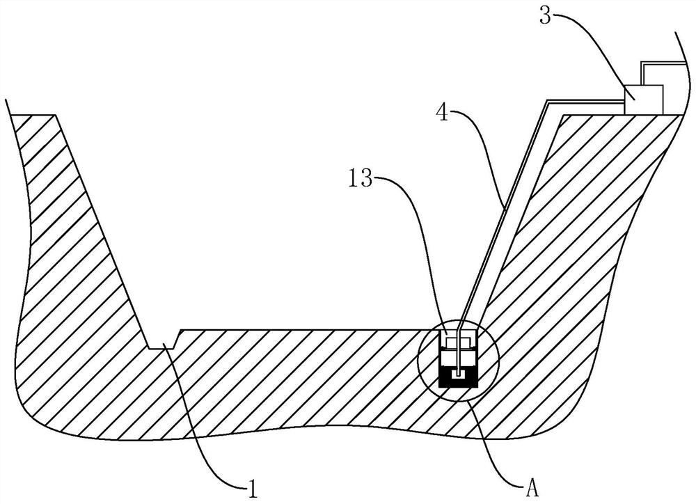
[0039] A foundation pit drainage structure, such as figure 1 As shown, it includes drainage ditches 1 arranged around the bottom of the foundation pit and sump wells 13 arranged at intervals along the drainage ditch 1 , and also includes a suction pump 3 connected to a suction pipe 4 extending into the bottom of the sump wells 13 . The bottom of drainage ditch 1 is lower than the bottom of foundation pit, and the bottom of water collecting well 13 is lower than the bottom of drainage ditch 1. Therefore groundwater and rainwater can flow in the drainage ditch 1, flow in the sump well 13 again, be sucked away by the water pump 3 at last;

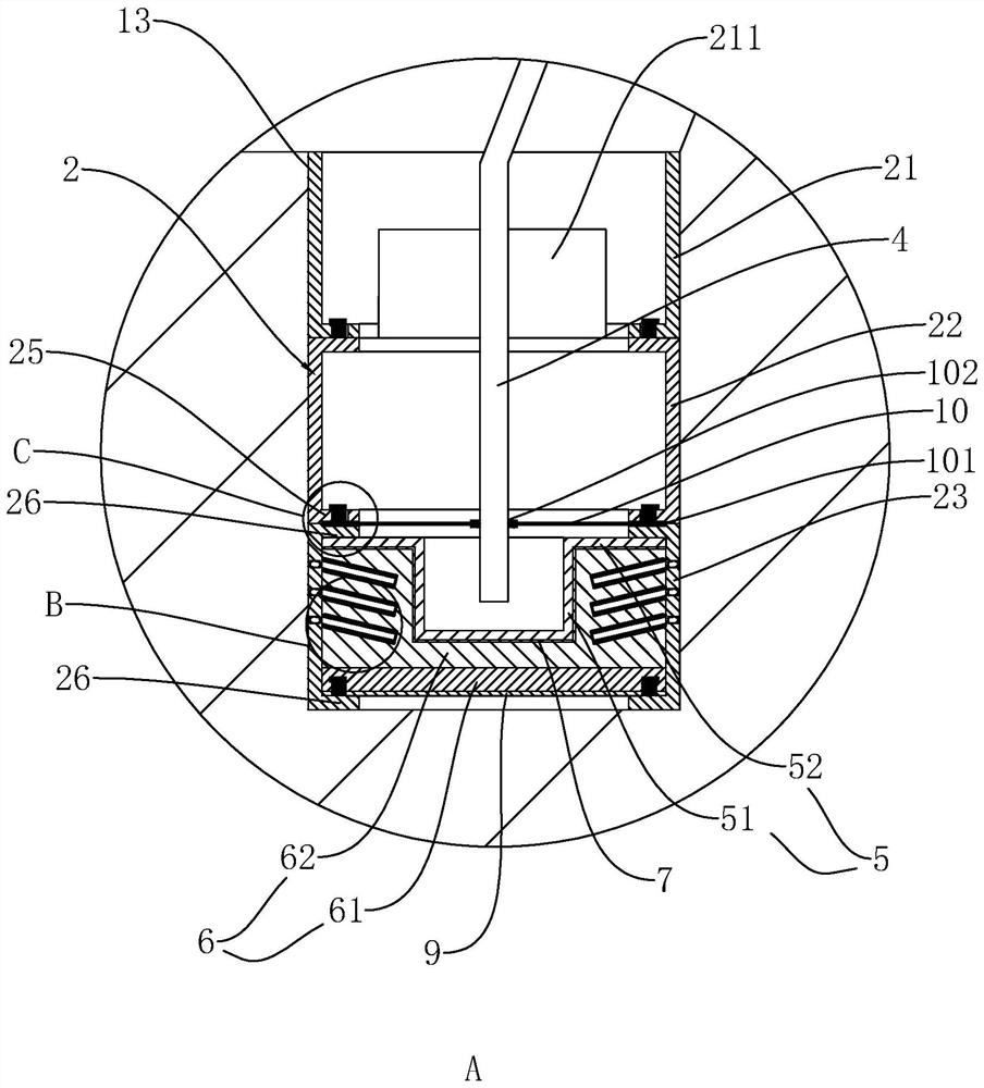
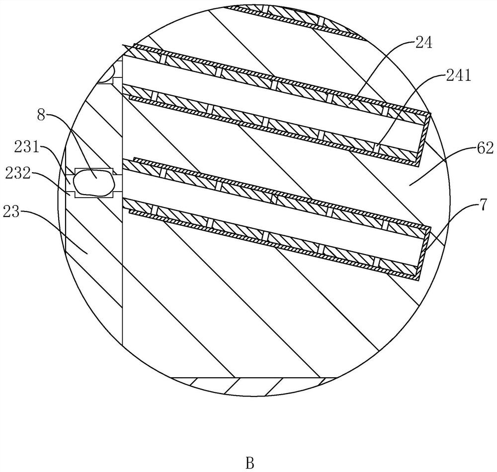
[0040] like figure 2 As shown, in order to prevent problems such as quicksand and collapse due to water seepage in the well wall of the water collection well 13, the inner wall of the water collection well 13 is closely attached to the support pipe 2 whose length is equal to the well depth. The support pipe 2 is divided into jacking pipe 21...

Embodiment 2

[0049] Different from Embodiment 1, the purification layer 62 includes the following raw materials in parts by weight: 40 parts of activated carbon, 30 parts of fine river sand, 16 parts of diatomaceous earth, and 50 parts of ceramsite filter material.

Embodiment 3

[0051] Different from Embodiment 1, the purification layer 62 includes the following raw materials in parts by weight: 35 parts of activated carbon, 25 parts of fine river sand, 13 parts of diatomaceous earth, and 40 parts of ceramsite filter material.


PUM


Abstract

The invention discloses a foundation pit dewatering and drainage structure. The key point of the technical scheme is that the structure comprises a drainage ditch and a water collecting well which arearranged at the bottom of a foundation pit, and also comprises a water suction pump and a water suction tube, a supporting tube is arranged in the water collecting well, the supporting tube is divided into a jacking tube, a connecting tube and a permeable tube from top to bottom, water inlets communicating with the drainage ditch are formed in the two sides, facing the drainage ditch, of the jacking tube, a plurality of water inlet holes are formed in the outer wall of the water permeable tube, a filter part made of a steel wire mesh is arranged on the inner side of the water permeable tube and comprises a filter cylinder located in the middle, a filter ring tightly attached to the inner wall of the water permeable tube is connected to the outer side of the upper end of the filter cylinder, the space between the filter part and the water permeable tube is filled with a filter material, and the water suction tube extends into the filter cylinder. Groundwater can permeate into the filter cylinder from the bottom of the water permeable tube and can also permeate into the filter cylinder from the side face of the water permeable tube, the circulation area is increased, then the watercollecting efficiency can be improved, and rapid dewatering and drainage are easily achieved.

Description

technical field [0001] The invention relates to the field of house construction, in particular to a foundation pit drainage structure. Background technique [0002] The foundation pit is an earth pit excavated at the foundation design position according to the base level and foundation plane size. When the depth of the foundation pit is below the natural groundwater table, groundwater will continuously infiltrate into the pit. In order to ensure that the foundation pit can be constructed under dry conditions, and to prevent problems such as slope instability, foundation quicksand, and pit bottom uplift, it is necessary to do a good job in drainage and drainage. At present, the methods of drainage and drainage of foundation pits include: open ditch plus water collection well for dewatering, light well point water purification, jet well point dewatering, etc. Among them, the method of open ditch plus water collection well for dewatering is the most common. [0003] The imple...

Claims


Application Information

Patent Timeline
Patent Type & Authority Patents(China)
IPC IPC(8): E02D19/10E02D17/02E02D19/06B01D29/11
CPCB01D29/115E02D17/02E02D19/06E02D19/10
Inventor 余温和何靓芳叶洋波程正贵
Owner 浙江立鹏建设有限公司
Learn More