A vertical single-stage pipeline centrifugal pump

A technology for centrifugal pumps and pipelines, applied in the field of vertical single-stage pipeline centrifugal pumps, which can solve problems such as rotor axial movement, vibration, and wear, and achieve the effects of reduced axial movement, large flow, and convenient cleaning of dirt

Active Publication Date: 2020-12-22
大庆市科利惠石油机械设备有限公司
View PDF6 Cites 1 Cited by
  • Summary
  • Abstract
  • Description
  • Claims
  • Application Information

AI Technical Summary

Problems solved by technology

[0005] With the above technical solution, since the exhaust hole is arranged on the pump body, the residual air in the impeller part can be completely emptied, so that the pipeline centrifugal pump can reach the working efficiency of 100% of the design value; but in this technical solution, there are still The following problems: During the operation of the centrifugal pump, because the liquid enters the impeller at low pressure and flows out at high pressure, the pressure on both sides of the impeller is unequal, resulting in an axial thrust pointing to the inlet direction, which will cause The rotor moves axially, causing wear and vibration; before starting the centrifugal pump, the pump casing and suction pipe must be filled with water, and then the motor must be started.

Method used


Image

  • A vertical single-stage pipeline centrifugal pump
  • A vertical single-stage pipeline centrifugal pump
  • A vertical single-stage pipeline centrifugal pump

Examples


Embodiment Construction

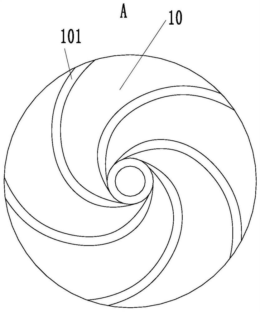
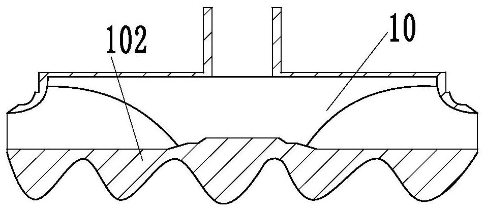
[0027] In order to make the technical means, creative features, goals and effects achieved by the present invention easy to understand, the following will further elaborate the present invention in conjunction with the specific embodiments. figure 1 as the benchmark.

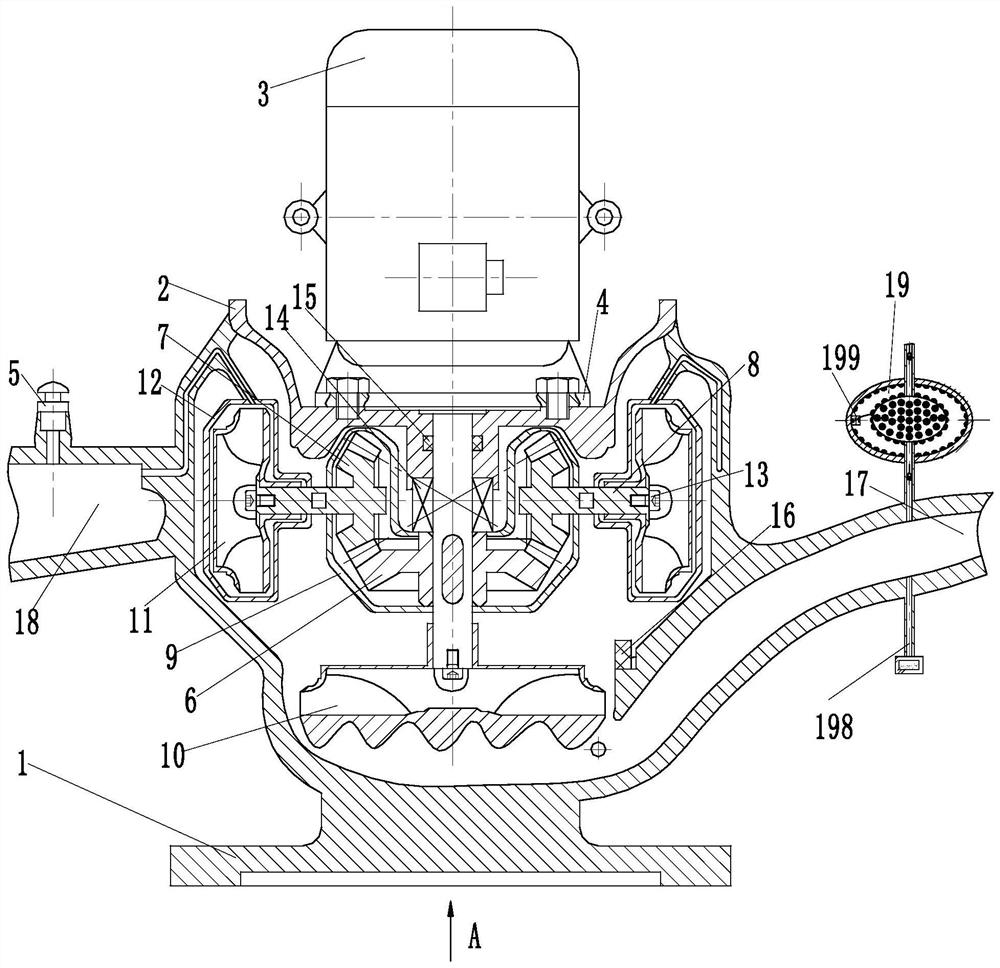
[0028] like Figure 1 to Figure 6 As shown, a vertical single-stage pipeline centrifugal pump according to the present invention includes a pump body 1, a pump cover 2, a motor 3, a flange 4, and a screw plug 5. The pump cover 2 is located on the upper side of the pump body 1, The pump cover 2 is fixedly connected with the pump body 1; the motor 3 is located on the upper side of the pump cover 2, and the motor 3 and the pump body 1 are fixedly connected through the flange 4; the screw plug 5 is located on the upper surface of the pump body 1, and the screw plug 5 is connected with the The pump body 1 is fixedly connected; it also includes the driving bevel gear 6, the driven bevel gear 7, the driven shaft 8, th...


PUM


Abstract

The invention belongs to the technical field of water supply equipment, and particularly relates to a vertical single-stage pipeline centrifugal pump. The centrifugal pump comprises a pump body, a pump cover, a motor, a driving bevel gear, driven bevel gears, a driven shaft, a bevel gear box body, a first impeller, a second impeller, an impeller box body and an impeller nut, wherein the pump bodyis fixedly connected with the pump cover, and the pump body is fixedly connected with the motor; the first impeller is fixedly connected with a motor shaft, and the driving bevel gear is located in the middle of the motor shaft and located on the upper portion of the first impeller; the driving bevel gear is fixedly connected with the motor shaft, and the driven bevel gears are connected with thedriving bevel gear through gear pairs; the four driven bevel gears are uniformly distributed on the driving bevel gear; the bevel gear box is located on the outer sides of the driving bevel gear and the driven bevel gears, and the bevel gear box body is used for sealing the driving bevel gear and the driven bevel gears; the driven shaft is fixedly connected with the bevel gears, and one end of thedriven shaft is fixedly connected with the second impeller through the impeller nut; the impeller box body is positioned on the outer side of the second impeller; and the impeller box body is used for sealing the second impeller.

Description

technical field [0001] The invention belongs to the technical field of water supply equipment, in particular to a vertical single-stage pipeline centrifugal pump. Background technique [0002] Pipeline pump is a kind of single-suction single-stage centrifugal pump. It is a vertical structure. Because the inlet and outlet are on the same straight line, and the diameter of the inlet and outlet is the same, it looks like a section of pipeline and can be installed at any position in the pipeline, so it is named pipeline. Pump, also known as booster pump. Structural features: It is a single-suction single-stage centrifugal pump, the inlet and outlet are the same and on the same straight line, perpendicular to the center line of the shaft, and it is a vertical pump. [0003] During the operation of the centrifugal pump, since the liquid enters the impeller at low pressure and flows out at high pressure, the pressure on both sides of the impeller is unequal, producing an axial thr...

Claims


Application Information

Patent Timeline
Patent Type & Authority Patents(China)
IPC IPC(8): F04D13/06F04D29/041F04D29/22F04D29/44F04D29/70
CPCF04D13/06F04D29/0416F04D29/2266F04D29/445F04D29/708
Inventor 姚潘涛王冬冬周俊满
Owner 大庆市科利惠石油机械设备有限公司
Why Eureka
Try Eureka