
Novel tubular preheater for carbon dioxide testbed and preheating method

A carbon dioxide and test bench technology, applied in indirect carbon dioxide emission reduction, combustion methods, lighting and heating equipment, etc., can solve the problem that the tube box equipment cannot realize the horizontal flow heat transfer of flue gas and air, and achieve perfect layout and simple manufacturing. , the effect of easy installation

Inactive Publication Date: 2019-08-02
HARBIN BOILER
View PDF3 Cites 1 Cited by
  • Summary
  • Abstract
  • Description
  • Claims
  • Application Information

AI Technical Summary

Problems solved by technology

[0004] Due to the increasingly fierce market competition and the increasingly perfect layout of boilers, the original tube and box equipment cannot realize the horizontal flow and heat exchange of flue gas and air

Method used


Image

  • Novel tubular preheater for carbon dioxide testbed and preheating method
  • Novel tubular preheater for carbon dioxide testbed and preheating method
  • Novel tubular preheater for carbon dioxide testbed and preheating method

Examples


Embodiment 1

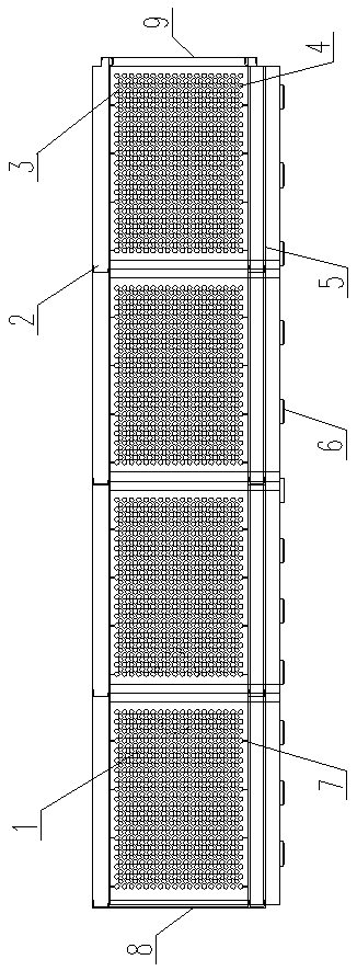
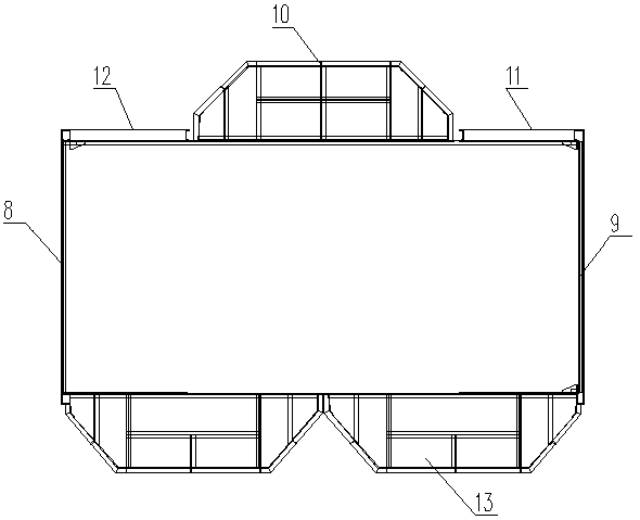
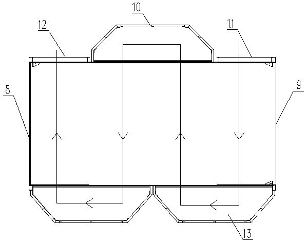
[0026] A new tubular preheater for a carbon dioxide test bench, which consists of: an intermediate tube bundle 1, the intermediate tube bundle includes two front and rear tube plates 3, and the tube plate has a set of horizontal round holes and vertical Installed on the sliding backing plate 6, pipes 4 are pierced in the horizontal circular holes between the front and rear two tube sheets, and a set of flat steel 7 is respectively fixed up and down the middle tube bundle, and above and below the tube sheets They are respectively fixed to the upper guard plate 2 and the lower guard plate 5, and the air duct communication box A10 is installed on one side of the middle tube bundle, and the air duct communication box B13 is installed on the other side.

Embodiment 2

[0028] According to the new tubular preheater for carbon dioxide test bench described in Example 1, the number of the intermediate tube bundles is one group, and the connection between them is welded between tube sheets, and the left end of the intermediate tube bundle is a smoke The air inlet 8, the right end is the flue gas outlet 9, the left side of the communication box A is the air duct outlet 12, and the right side is the air duct inlet 11.

Embodiment 3

[0030] According to the novel tubular preheater for a carbon dioxide test bench described in embodiment 1 or 2, the tube sheet is connected to the steel structure through the sliding backing plate, and the sliding backing plate includes an upper backing plate, The upper backing plate is connected with the lower backing plate through a slideway, and the lower backing plate is fixed with the steel structure.


PUM


Abstract

The invention relates to a novel tubular preheater for a carbon dioxide testbed and a preheating method. As a result of increasingly competitive market competition and increasingly improvement of arrangement forms of boilers, original channel equipment cannot achieve horizontal flowing heat exchange of flue gas and air. The preheater comprises a middle tube bundle (1) which comprises front and back tube plates (3). Each tube plate is provided with a horizontal round hole and is vertically mounted on a sliding base plate (6), a tube (4) is threaded in the horizontal round holes between the front and back tube plates, steel flat (7) is separately fixed above and below the middle tube bundle, the upper and lower sides of the tube plate are separately fixed to an upper protecting plate (2) anda lower protecting plate (5), an air duct communicating box A (10) is mounted on one side of the middle tube bundle and an air duct communicating box B (13) is mounted on the other side of the middletube bundle. The invention provides the novel tubular preheater for the carbon dioxide testbed.

Description

[0001] Technical field: [0002] The invention relates to a novel tubular preheater and a preheating method for a carbon dioxide test bench. [0003] Background technique: [0004] Due to the increasingly fierce market competition and the increasingly perfect layout of boilers, the original tube and box equipment cannot realize the horizontal flow and heat exchange of flue gas and air. [0005] Invention content: [0006] The purpose of the present invention is to provide a new type of tube preheating and preheating method for carbon dioxide test bench. [0007] Above-mentioned purpose realizes by following technical scheme: [0008] A new tubular preheater for a carbon dioxide test bench, which consists of: an intermediate tube bundle, the intermediate tube bundle includes two front and rear tube plates, and the tube plate has a group of horizontal round holes and is vertically installed on the On the sliding backing plate, pipes are pierced in the horizontal round holes be...

Claims


Application Information

Patent Timeline
Patent Type & Authority Applications(China)
IPC IPC(8): F23L15/04
CPCF23L15/04F23L2900/15043Y02E20/34
Inventor 徐琳吕健管思嘉王宏生刘琳琳
Owner HARBIN BOILER
Learn More